UTC TL1451 LINEAR INTEGRATED CIRCUIT Handbook
Summary
The TL1451 is a highly advanced integrated circuit designed for complete, synchronized Pulse-Width Modulation (PWM) power control, ideal for robust power supply regulation. This comprehensive manual serves as an essential technical reference for electrical engineers and hardware designers creating efficient power converters. It covers detailed operational parameters, absolute maximum ratings, pin configurations, and signal timing diagrams, ensuring correct implementation of features like undervoltage lock-out and dead-time protection in your next project.
Page 1 Text Content
查询TL1451供应商
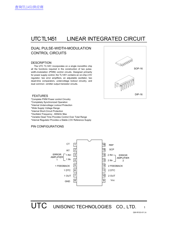
UTC TL1451 LINEAR INTEGRATED CIRCUIT DUAL PULSE-WIDTH-MODULATION CONTROL CIRCUITS
DESCRIPTION The UTC TL1451 incorporates on a single monolithic chip
all the functions required in the construction of two pulse- SOP-16
width-modulation (PWM) control circuits. Designed primarily for power supply control, the TL1451 contains an on-chip 2.5V regulator, two error amplifiers, an adjustable oscillator, two dead-time comparators, undervoltage lockout circuitry, and dual common –emitter output transistor circuits.
DIP-16
FEATURES *Complete PWM Power control Circuitry *Completely Synchronized Operation *Internal Undervoltage Lockout Protection *Wide Supply Voltage Range *Internal Short-Circuit Protection *Oscillator Frequency …500k Hz Max *Variable Dead Time Provides Control Over Total Range *Internal Regulator Provides a Stable 2.5V Reference Supply
PIN CONFIGURATIONS
ERROR 1 IN+ 2 IN+
ERROR
AMPLIFIER
AMPLIFIER
1 IN-
2 IN-
1 FEEDBACK 2 FEEDBACK
1 DTC 2 DTC
1 OUT 2 OUT
UTC UNISONIC TECHNOLOGIES CO., LTD.
QW-R103-011,A
Page Summary Contents For UTC TL1451 LINEAR INTEGRATED CIRCUIT Handbook
Manual Details
| Brand | Linear |
|---|---|
| Pages | 5 |
| File Size | 127.60 KB |
| Published | May 29, 2026 |
Enter the captcha to get the download link:

Frequently Asked Questions
What is the recommended supply voltage range for the TL1451?
The device can operate over a wide supply voltage range, recommended between 3.6V and 40V.
Does the TL1451 include built-in protection features?
Yes, it incorporates undervoltage lockout circuitry and also includes short-circuit protection (SCP).
What is the maximum oscillator frequency supported by this circuit?
The module supports an oscillator frequency up to 500 kHz.