Toshiba VNL08C351-INV Data Handbook
Summary
Engineered for display system integrators, this manual provides comprehensive technical documentation and wiring schematics for an essential inverter unit. It details critical electrical specifications, including input voltage ranges, operational current limits, frequency standards, and thermal tolerances. This guide is designed for engineers who require precise mechanical dimensions, connection pin assignments, and setup parameters necessary for the reliable integration of display backlighting components into specialized equipment.
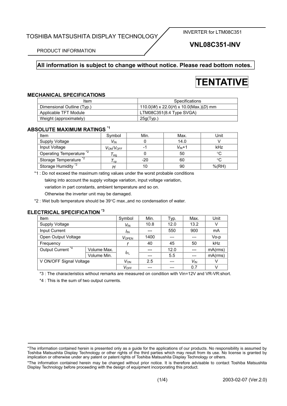
Page 1 Text Content
INVERTER for LTM08C351
TOSHIBA MATSUSHITA DISPLAY TECHNOLOGY
VNL08C351-INV
PRODUCT INFORMATION
All information is subject to change without notice. Please read bottom notes.
TENTATIVE
MECHANICAL SPECIFICATIONS
Item Specifications
Dimensional Outline (Typ.) 110.0(W) x 22.0(H) x 10.0(Max.)(D) mm Applicable TFT Module LTM08C351(8.4 Type SVGA) Weight (approximately) 25g(Typ.)
ABSOLUTE MAXIMUM RATINGS *1 Item Symbol Min. Max. Unit Supply Voltage VIN 0 14.0 V Input Voltage VON/VOFF -1 VIN+1 k Hz Operating Temperature *2 Tstg 0 50 °C Storage Temperature *2 Top -20 60 °C Storage Humidity *2 H 10 90 %(RH) *1 : Do not exceed the maximum rating values under the worst probable conditions taking into account the supply voltage variation, input voltage variation, variation in part constants, ambient temperature and so on. Otherwise the inverter unit may be damaged. *2 : Wet bulb temperature should be 39°C max.,and no condensation of water.
ELECTRICAL SPECIFICATION *3 Item Symbol Min. Typ. Max. Unit Supply Voltage VIN 10.8 12.0 13.2 V Input Current IIN --- 550 900 m A Open Output Voltage VOPEN 1400 --- --- Vo-p Frequency f 40 45 50 k Hz
Volume Max. --- 12.0 --- m A(rms) Output Current *4
Volume Min. --- 5.5 --- m A(rms)
VON 2.5 --- VIN V V ON/OFF Signal Voltage VOFF --- --- 0.7 V
*3 : The characteristics without remarks are measured on condition with Vin=12V and VR-VR:short. *4 : This is the sum of two output currents.
*The information contained herein is presented only as a guide for the applications of our products. No responsibility is assumed by Toshiba Matsushita Display Technology or other rights of the third parties which may result from its use. No license is granted by implication or otherwise under any patent or patent rights of Toshiba Matsushita Display Technology or others. *The information contained herein may be changed without prior notice. It is therefore advisable to contact Toshiba Matsushita Display Technology before proceeding with the design of equipment incorporating this product.
(1/4) 2003-02-07 (Ver.2.0)
Page Summary Contents For Toshiba VNL08C351-INV Data Handbook
Manual Details
| Brand | Toshiba |
|---|---|
| Pages | 4 |
| File Size | 39.02 KB |
| Published | June 01, 2026 |
Enter the captcha to get the download link:

Frequently Asked Questions
What is the recommended operating temperature range?
The operating temperature range is from 0 °C to 50 °C.
What are the maximum input voltage and current specifications?
Maximum rated supply input voltage (VIN) is 14.0 V, and the maximum input current is 900 mA.
How should I handle connecting the GND pin?
You must connect the GND pin to ground; do not leave it as a no-connect or connect it with high impedance.