Toshiba TOTX179 User Guide
Summary
The TOTX179 is a high-performance Fiber Optic Transmitting Module designed specifically for reliable signal connectivity in digital audio equipment. This comprehensive manual provides essential technical specifications, including detailed electrical/optical characteristics, maximum operational ratings, and mechanical mounting data. Whether you are an electronics designer or engineer building sophisticated audio interfaces, this guide ensures safe integration of the module into your professional systems while detailing handling precautions for optimal performance.
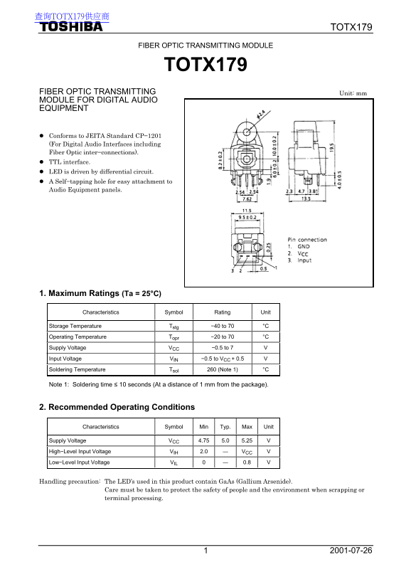
Page 1 Text Content
查询TOTX179供应商
TOTX179
FIBER OPTIC TRANSMITTING MODULE
TOTX179
FIBER OPTIC TRANSMITTING Unit: mm MODULE FOR DIGITAL AUDIO EQUIPMENT
Conforms to JEITA Standard CP−1201 (For Digital Audio Interfaces including Fiber Optic inter−connections). TTL interface. LED is driven by differential circuit. A Self−tapping hole for easy attachment to Audio Equipment panels.
1. Maximum Ratings (Ta = 25°C)
Characteristics Symbol Rating Unit
Storage Temperature Tstg −40 to 70 °C Operating Temperature Topr −20 to 70 °C Supply Voltage VCC −0.5 to 7 V Input Voltage VIN −0.5 to VCC + 0.5 V Soldering Temperature Tsol 260 (Note 1) °C
Note 1: Soldering time ≤ 10 seconds (At a distance of 1 mm from the package).
2. Recommended Operating Conditions
Characteristics Symbol Min Typ. Max Unit
Supply Voltage VCC 4.75 5.0 5.25 High−Level Input Voltage VIH 2.0 ― VCC V Low−Level Input Voltage VIL 0 ― 0.8 V
Handling precaution: The LED’s used in this product contain Ga As (Gallium Arsenide).
Care must be taken to protect the safety of people and the environment when scrapping or terminal processing.
Page Summary Contents For Toshiba TOTX179 User Guide
Manual Details
| Brand | Toshiba |
|---|---|
| Pages | 5 |
| File Size | 109.60 KB |
| Published | June 02, 2026 |
Enter the captcha to get the download link:

Frequently Asked Questions
What are the recommended operating voltages for this module?
The typical supply voltage (Vcc) ranges from 4.75 V to 5.25 V.
How should I handle soldering precautions for this module?
It is best to solder without mounting the optical module on the board, then mount it manually after cleaning the board.
What are the potential risks associated with disposing of this product?
The LED contains GaAs (Gallium Arsenide), which is toxic. Do not dispose of it with other industrial or domestic waste.