Toshiba TLP763J User Guide
Summary
This high-reliability optocoupler utilizes a GaAs infrared LED paired with a photo-triac, providing robust electrical isolation for controlling power circuits. Designed as a solid state relay driver, it safely couples signals across challenging voltage levels up to 4000 Vrms. The manual offers comprehensive technical specifications, including maximum ratings, operating curves, and compliance details (UL/BSI standards). This component is essential for electronics engineers and designers building industrial controls or household equipment requiring reliable and safe signal isolation.
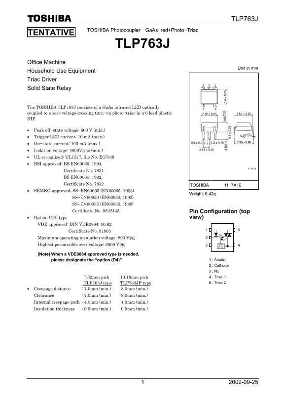
Page 1 Text Content
TLP763J
TOSHIBA Photocoupler Ga As Ired+Photo−Triac TENTATIVE
TLP763J
Office Machine
Unit in mm
Household Use Equipment Triac Driver Solid State Relay
The TOSHIBA TLP763J consists of a Ga As infrared LED optically coupled to a zero voltage crossing turn−on photo−triac in a 6 lead plastic DIP.
Peak off−state voltage: 600 V (min.) Trigger LED current: 10 m A (max.) On−state current: 100 m A (max.) Isolation voltage: 4000Vrms (min.) UL recognized: UL1577, file No. E67349 BSI approved: BS EN60065: 1994, Certificate No. 7831 BS EN60065: 1992, Certificate No. 7832
TOSHIBA 11−7A10
SEMKO approved: SS−EN60065 (EN60065, 1993)
Weight: 0.42g
SS−EN60950 (EN60950, 1992) SS−EN60335 (EN60335, 1988) Certificate No. 9522145 Pin Configuration (top
Option (D4) type view)
VDE approved: DIN VDE0884, 06.92 Certificate No. 91803 Maximum operating insulation voltage: 890 VPK Highest permissible over voltage: 6000 VPK 3 ZC
(Note) When a VDE0884 approved type is needed,
please designate the “option (D4)” 1 : Anode 2 : Cathode 3 : Nc 7.62mm pich 10.16mm pich 4 : Triac 1 TLP763J type TLP763JF type 6 : Triac 2
Creepage distance : 7.0mm (min.) 8.0mm (min.) Clearance : 7.0mm (min.) 8.0mm (min.) Internal creepage path : 4.0mm (min.) 4.0mm (min.) Insulation thickness : 0.5mm (min.) 0.5mm (min.)
Page Summary Contents For Toshiba TLP763J User Guide
Manual Details
| Brand | Toshiba |
|---|---|
| Pages | 6 |
| File Size | 127.22 KB |
| Published | May 31, 2026 |
Enter the captcha to get the download link:

Frequently Asked Questions
What is the minimum electrical isolation voltage of the coupler?
The minimum isolation voltage listed for AC operation is 4000Vrms.
What should I know about handling or disposal of this product?
GaAs dust and fumes are toxic. Do not break, cut, pulverize the product, or use chemicals to dissolve it.
What types of applications are restricted regarding usage (Unintended Usage)?
The products are not intended for equipment requiring exceptionally high quality/reliability, such as medical instruments or safety devices.
How is the Anode pin identified on the device?
According to the pin configuration diagram, the anode connection point is Pin 1.