Toshiba TOSHIBA TIM7785-8L MICROWAVE POWER GaAs FET Low Distortion Internally Matched Power GaAs FETs (C-Band) Data Handbook
Summary
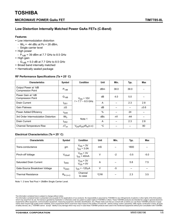
This high-performance Microwave Power GaAs FET is designed for robust amplification in C-Band frequency applications (7.7–8.5 GHz), offering exceptional power output combined with very low intermodulation distortion. Ideal for professional engineers developing sensitive communication and microwave equipment, this component ensures superior signal integrity. The manual provides comprehensive coverage of key RF performance specifications, electrical characteristics, and thermal ratings necessary for accurate design integration into advanced circuitry.
Page 1 Text Content
TOSHIBA MICROWAVE POWER Ga As FET TIM7785-8L
Low Distortion Internally Matched Power Ga As FETs (C-Band)
Features Low intermodulation distortion IM = -44 d Bc at Po = 28 d Bm, Single carrier level High power
= 39 d Bm at 7.7 GHz to 8.5 GHz 1d B High gain = 5.0 d B at 7.7 GHz to 8.5 GHz 1d B Broad band internally matched Hermetically sealed package
RF Performance Specifications (Ta = 25 C)
Characteristics Symbol Condition Unit Min. Typ. Max
Output Power at 1d B
d Bm 38.0 39.0
Compression Point
Power Gain at 1d B
Compression Point = 10V
DS f = 7.7 ~ 8.5 GHz
Drain Current 2.3 2.8
Gain Flatness d B 0.6
Power Added Efficiency
3rd Order Intermodulation Distortion IM d Bc -41 -44
Note 1
Drain Current 2.3 2.8
Channel-Temperature Rise x I x R (c-c)
ch DS DS th
Electrical Characteristics (Ta = 25 C)
Characteristic Symbol Condition Unit Min. Typ. Max
= 3V DS
Trans-conductance gm m S
= 3.0A DS
= 3V DS
Pinch-off Voltage -2 -3.5 -5.0
GSoff
= 40m A DS
= 3V DS
Saturated Drain Current 5.8 7.5
= 0V GS
Gate-Source Breakdown Voltage = -120 -5
GSO GS
Channel
Thermal Resistance C/W 2.3 3.5
th (c-c)
to case
Note 1: 2 tone Test Pout = 28d Bm Single Carrier Level.
The information contained here is subject to change without notice. The information contained herein is presented only as guide for the applications of our products. No responsibility is assumed by TOSHIBA for any infringements of patents or other rights of the third parties which may result from its use. No license is granted by implication or otherwise under any patent or patent rights of TOSHIBA or others. These TOSHIBA products are intended for usage in general electronic equipments (office equipment, communication equipment, measuring equipment, domestic electrification, etc.) Please make sure that you consult with us before you use these TOSHIBA products in equip- ments which require high quality and/or reliability, and in equipments which could have major impact to the welfare of human life (atomic energy control, spaceship, traffic signal, combustion control, all types of safety devices, etc.). TOSHIBA cannot accept liability to any damage which may occur in case these TOSHIBA products were used in the mentioned equipments without prior consultation with TOSHIBA.
TOSHIBA CORPORATION MW51080196 1/5
Page Summary Contents For Toshiba TOSHIBA TIM7785-8L MICROWAVE POWER GaAs FET Low Distortion Internally Matched Power GaAs FETs (C-Band) Data Handbook
Manual Details
| Brand | Toshiba |
|---|---|
| Pages | 5 |
| File Size | 138.98 KB |
| Published | June 02, 2026 |
Enter the captcha to get the download link:

Frequently Asked Questions
Can I use this FET in safety or high-reliability equipment?
No, caution is advised; consultants are recommended for life-critical applications like traffic signals or atomic energy control.
What are the absolute maximum ratings (DSV and DIV)?
The Drain-Source Voltage (Vds) max rating is 15V, and the Drain Current (Id) max rating is 8A.
How should I handle soldering this component?
Ensure the soldering iron is grounded and do not exceed 10 seconds of operation at 260°C.