TOSHIBA MT3S14FS User Guide and Technical Specifications (Part 1)
Summary
The MT3S14FS is a high-performance NPN epitaxial planar transistor designed for critical RF applications in the VHF to UHF frequency bands. It excels as both a low-noise amplifier and a buffer, offering superior operational characteristics required for sensitive equipment design. This documentation provides comprehensive technical data, including detailed microwave parameters like insertion gain and noise figure (NF), alongside electrical specifications, absolute maximum ratings, and essential handling precautions. It is specifically intended for RF electronics engineers who require reliable components for professional system development.
Page 1 Text Content
MT3S14FS
TOSHIBA Transistor Silicon NPN Epitaxial Planar Type
MT3S14FS
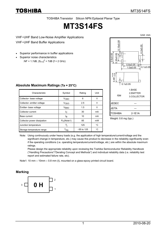
Unit: mm
VHF~UHF Band Low-Noise Amplifier Applications VHF~UHF Band Buffer Applications
• Superior performance in buffer applications • Superior noise characteristics :NF = 1.7d B, |S21e|2 = 7d B (f = 2 GHz)
Absolute Maximum Ratings (Ta = 25°C)
1.BASE
Characteristic Symbol Rating Unit 2.EMITTER
3.COLLECTOR
Collector- base voltage VCBO 6 V
Collector- emitter voltage VCEO 2.5 V JEDEC ― Emitter- base voltage VEBO 1.5 V
JEITA ―
Collector current IC 30 m A
TOSHIBA 2-1E1A +0 .0 0. -0 .0
Base current IB 10 m A
Weight: 0.6 mg (typ.)
Collector power dissipation PC(Note1) 85 m W
Junction temperature Tj 125 °C
Storage temperature range Tstg −55 to 125 °C
Note: Using continuously under heavy loads (e.g. the application of high temperature/current/voltage and the significant change in temperature, etc.) may cause this product to decrease in the reliability significantly even
if the operating conditions (i.e. operating temperature/current/voltage, etc.) are within the absolute maximum 0. 2± 0.
ratings. Please design the appropriate reliability upon reviewing the Toshiba Semiconductor Reliability Handbook (“Handling Precautions”/“Derating Concept and Methods”) and individual reliability data (i.e. reliability test report and estimated failure rate, etc).
Note1: 10 mm × 10mm × 0.8 mm (t), mounted on a glass-epoxy printed circuit board.
Marking
Page Summary Contents For TOSHIBA MT3S14FS User Guide and Technical Specifications (Part 1)
Manual Details
| Brand | Toshiba |
|---|---|
| Pages | 3 |
| File Size | 152.49 KB |
| Published | May 28, 2026 |
Enter the captcha to get the download link:

Frequently Asked Questions
What precautions should I take when handling this device?
The device is sensitive to electrostatic discharge; ensure tools are grounded and wear anti-static clothing when handling it.
What is the minimum Noise Figure for low-noise amplification at 2 GHz?
The minimum noise figure (NF) specified for an application at f = 2 GHz is 1.7 dB.
How should I ensure reliable operation under extreme conditions?
Consult the Toshiba Semiconductor Reliability Handbook and individual reliability data to design appropriate derating, especially when operating under heavy loads.
Does this product comply with RoHS directives?
Contact your TOSHIBA sales representative for specific details regarding its environmental compliance status like RoHS.