Texas Instruments XTR112 XTR1144-20mA Current Transmitters with Sensor Excitation and Linearization
Summary
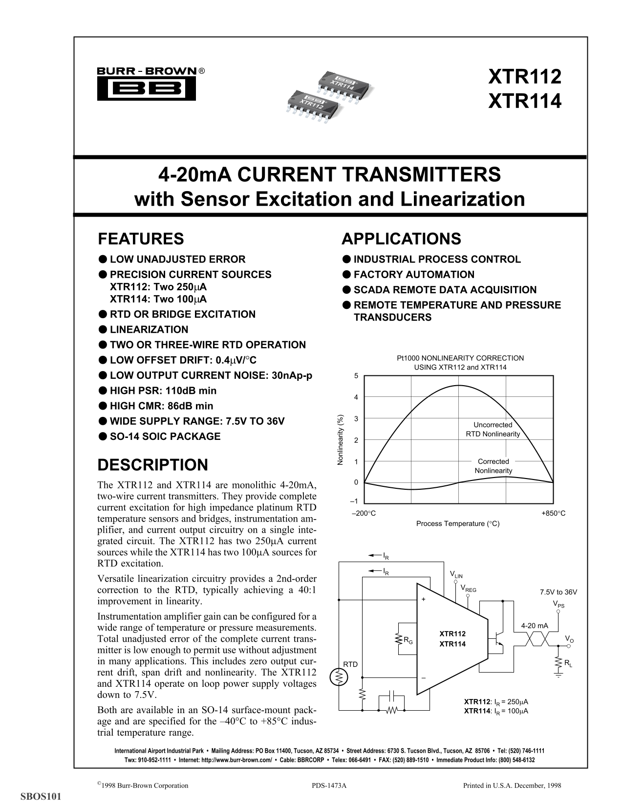
The XTR112/XTR114 series are specialized monolithic 4-20mA current transmitters designed for high-precision industrial process control. These transducers integrate RTD excitation, comprehensive signal amplification, and advanced linearization circuitry onto a single chip. They are engineered for SCADA remote data acquisition and factory automation monitoring of temperature and pressure in demanding environments (–40°C to +85°C). This summary provides technical details on electrical specifications, low drift performance, and ideal applications for professional engineers and industrial system integrators.
Page 1 Text Content
XTR114 XTR112 XTR112
XTR114
4-20m A CURRENT TRANSMITTERS with Sensor Excitation and Linearization FEATURES APPLICATIONS LOW UNADJUSTED ERROR INDUSTRIAL PROCESS CONTROL PRECISION CURRENT SOURCES FACTORY AUTOMATION XTR112: Two 250µA
SCADA REMOTE DATA ACQUISITION
XTR114: Two 100µA
REMOTE TEMPERATURE AND PRESSURE
RTD OR BRIDGE EXCITATION
TRANSDUCERS
LINEARIZATION
on lin ea rit
TWO OR THREE-WIRE RTD OPERATION
Pt1000 NONLINEARITY CORRECTION
LOW OFFSET DRIFT: 0.4µV/°C
USING XTR112 and XTR114
LOW OUTPUT CURRENT NOISE: 30n Ap-p HIGH PSR: 110d B min HIGH CMR: 86d B min WIDE SUPPLY RANGE: 7.5V TO 36V
Uncorrected RTD Nonlinearity
SO-14 SOIC PACKAGE
Corrected
DESCRIPTION
Nonlinearity
The XTR112 and XTR114 are monolithic 4-20m A, two-wire current transmitters. They provide complete
current excitation for high impedance platinum RTD
temperature sensors and bridges, instrumentation am-
Process Temperature (°C)
plifier, and current output circuitry on a single inte- grated circuit. The XTR112 has two 250µA current sources while the XTR114 has two 100µA sources for
RTD excitation.
Versatile linearization circuitry provides a 2nd-order
correction to the RTD, typically achieving a 40:1 7.5V to 36V improvement in linearity. VPS Instrumentation amplifier gain can be configured for a
wide range of temperature or pressure measurements. 4-20 m A
XTR112
Total unadjusted error of the complete current trans- RG VO
XTR114
mitter is low enough to permit use without adjustment in many applications. This includes zero output cur- RL
rent drift, span drift and nonlinearity. The XTR112 and XTR114 operate on loop power supply voltages down to 7.5V.
XTR112: IR = 250µA
Both are available in an SO-14 surface-mount pack- XTR114: IR = 100µA age and are specified for the –40°C to +85°C indus- trial temperature range. International Airport Industrial Park • Mailing Address: PO Box 11400, Tucson, AZ 85734 • Street Address: 6730 S. Tucson Blvd., Tucson, AZ 85706 • Tel: (520) 746-1111 Twx: 910-952-1111 • Internet: http://www.burr-brown.com/ • Cable: BBRCORP • Telex: 066-6491 • FAX: (520) 889-1510 • Immediate Product Info: (800) 548-6132
©1998 Burr-Brown Corporation
PDS- 473A XTR112, XTR114 Printed in U.S.A. December, 1998
SBOS101
Page Summary Contents For Texas Instruments XTR112 XTR1144-20mA Current Transmitters with Sensor Excitation and Linearization
Manual Details
| Brand | Texas Instruments |
|---|---|
| Pages | 18 |
| File Size | 210.72 KB |
| Published | June 22, 2026 |
Enter the captcha to get the download link:

Frequently Asked Questions
What is the primary difference between the XTR112 and XTR114 models?
The XTR112 features two 250μA current sources, while the XTR114 utilizes two 100μA sources for RTD excitation.
What is the maximum industrial temperature range for these transmitters?
They are specified to operate within an industrial temperature range of minus 40°C up to plus 85°C.
What loop power supply voltage can the XTR112 and XTR114 use?
Both units operate on loop power supply voltages that go down to a minimum of 7.5V.
Does the unit require manual adjustment upon installation in most settings?
No, the complete transmitter has low unadjusted error, which permits use without further adjustment in many applications.