Texas Instruments TPIC1021 Data Sheet / Manual
Summary
The TPIC1021 is a robust LIN (Local Interconnect Network) physical interface transceiver designed for low-speed, single-wire car networking. This manual details its integration of advanced protection and transceiving features necessary for demanding automotive environments, including high voltage handling (-40V to +40V) and immunity to transients (ISO 7637). It provides developers with a reliable solution that features wake-up capability, low power quiescent current modes, and full compliance with the LIN Physical Layer Specification Revision 2.0. This component is ideal for implementing robust in-vehicle communication systems.
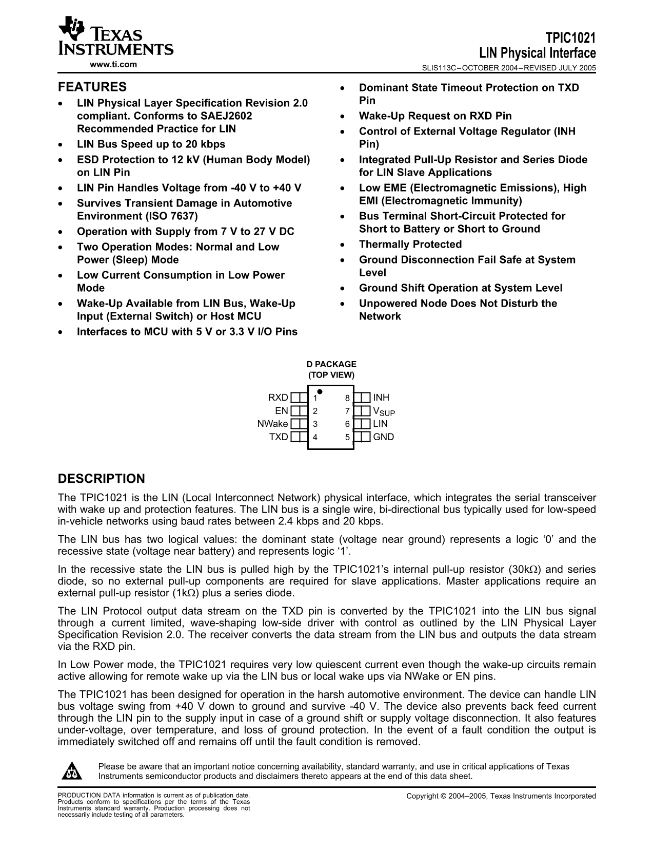
Page 1 Text Content
TPIC1021
LIN Physical Interface
www.ti.com
SLIS113C–OCTOBER 2004–REVISED JULY
FEATURES Dominant State Timeout Protection on TXD
LIN Physical Layer Specification Revision 2.0
compliant. Conforms to SAEJ2602 Wake-Up Request on RXD Pin
Recommended Practice for LIN
Control of External Voltage Regulator (INH
LIN Bus Speed up to kbps Pin)
ESD Protection to k V (Human Body Model) Integrated Pull-Up Resistor and Series Diode
on LIN Pin for LIN Slave Applications
LIN Pin Handles Voltage from -40 to +40 Low EME (Electromagnetic Emissions), High
EMI (Electromagnetic Immunity)•
Survives Transient Damage in Automotive
Environment (ISO 7637) Bus Terminal Short-Circuit Protected for
Short to Battery or Short to Ground•
Operation with Supply from to DC
Thermally Protected•
Two Operation Modes: Normal and Low
Power (Sleep) Mode Ground Disconnection Fail Safe at System
Level•
Low Current Consumption in Low Power
Mode Ground Shift Operation at System Level
Wake-Up Available from LIN Bus, Wake-Up Unpowered Node Does Not Disturb the
Input (External Switch) or Host MCU Network
Interfaces to MCU with or 3.3 I/O Pins
D PACKAGE (TOP VIEW)
RXD INH EN VSUP NWake LIN TXD GND
DESCRIPTION
The TPIC1021 is the LIN (Local Interconnect Network) physical interface, which integrates the serial transceiver
with wake up and protection features. The LIN bus is single wire, bi-directional bus typically used for low-speed
in-vehicle networks using baud rates between 2.4 kbps and kbps.
The LIN bus has two logical values: the dominant state (voltage near ground) represents logic ‘0’ and the
recessive state (voltage near battery) and represents logic ‘1’.
In the recessive state the LIN bus is pulled high by the TPIC1021’s internal pull-up resistor (30kΩ) and series
diode, so no external pull-up components are required for slave applications. Master applications require an
external pull-up resistor (1kΩ) plus series diode.
The LIN Protocol output data stream on the TXD pin is converted by the TPIC1021 into the LIN bus signal
through current limited, wave-shaping low-side driver with control as outlined by the LIN Physical Layer
Specification Revision 2.0. The receiver converts the data stream from the LIN bus and outputs the data stream
via the RXD pin.
In Low Power mode, the TPIC1021 requires very low quiescent current even though the wake-up circuits remain
active allowing for remote wake up via the LIN bus or local wake ups via NWake or EN pins.
The TPIC1021 has been designed for operation in the harsh automotive environment. The device can handle LIN
bus voltage swing from +40 down to ground and survive -40 V. The device also prevents feed current
through the LIN pin to the supply input in case of ground shift or supply voltage disconnection. It also features
under-voltage, over temperature, and loss of ground protection. In the event of fault condition the output is
immediately switched off and remains off until the fault condition is removed.
Please be aware that an important notice concerning availability, standard warranty, and use in critical applications of Texas
Instruments semiconductor products and disclaimers thereto appears at the end of this data sheet.
PRODUCTION DATA information is current as of publication date. Copyright 2004–2005, Texas Instruments Incorporated
Products conform to specifications per the terms of the Texas
Instruments standard warranty. Production processing does not
necessarily include testing of all parameters.
Page Summary Contents For Texas Instruments TPIC1021 Data Sheet / Manual
Manual Details
| Brand | Texas Instruments |
|---|---|
| Pages | 14 |
| File Size | 217.71 KB |
| Published | July 12, 2026 |
Enter the captcha to get the download link:

Frequently Asked Questions
Is external pull-up required for slave mode applications?
No. The internal pull-up resistor and diode are sufficient in slave applications.
What is the operational voltage range for this device?
It operates with a supply from 7 V to 27 V DC, and can handle LIN bus voltage swings from +40 V down to -40 V.
How does it support low power operation?<
Yes, it features ESD protection to 12 kV, Ground Disconnection Fail Safe, and protects against transient damage in automotive environments.