Texas Instruments TMS27C210A 65536 BY 16-BIT UV ERASABLE TMS27PC210A 65536 BY 16-BIT PROGRAMMABLE READ-OFF MEMORY
Summary
Explore high-speed, reliable non-volatile memory with the TMS27C/TMS27PC series EPROM and PROM chips. These 65K x 16-bit components utilize power-saving CMOS technology, featuring TTL-compatible I/O for seamless integration into microprocessor-based systems. This manual provides comprehensive technical guidance, detailing operational modes (Read, Program, Standby), detailed pinouts, electrical specifications, and environmental considerations necessary for optimal system design. Ideal for engineers developing robust electronic products requiring durable, high-performance memory storage solutions.
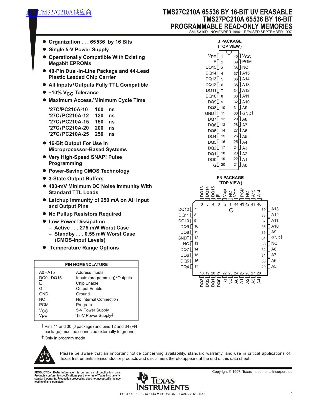
Page 1 Text Content
查询TMS27C210A供应商 TMS27C210A 65536 BY 16-BIT UV ERASABLE
TMS27PC210A 65536 BY 16-BIT
PROGRAMMABLE READ-ONLY MEMORIES SMLS310D– NOVEMBER 1990 – REVISED SEPTEMBER 1997
Organization 65536 by 16 Bits J PACKAGE (TOP VIEW)
Single 5-V Power Supply
VPP VCC
Operationally Compatible With Existing
Megabit EPROMs
DQ15 NC
40-Pin Dual-In-Line Package and 44-Lead
DQ14 A15
Plastic Leaded Chip Carrier
DQ13 A14 All Inputs/Outputs Fully TTL Compatible DQ12 A13 DQ11 A12
±10% VCC Tolerance
DQ10 A11
Maximum Access/Minimum Cycle Time
DQ9 A10 DQ8 A9
’27C/PC210A-10 ns
GND† GND†
’27C/PC210A-12 ns
DQ7 A8
’27C/PC210A-15 ns
DQ6 A7
’27C/PC210A-20 ns
DQ5 A6
’27C/PC210A-25 ns
DQ4 A5 DQ3 A4
16-Bit Output For Use in
DQ2 A3
Microprocessor-Based Systems
DQ1 A2
Very High-Speed SNAP! Pulse
DQ0 A1
Programming
Power-Saving CMOS Technology
3-State Output Buffers FN PACKAGE (TOP VIEW)
400-m V Minimum DC Noise Immunity With Standard TTL Loads Latchup Immunity of 250 m A on All Input and Output Pins
DQ12 A13
No Pullup Resistors Required DQ11 A12
DQ10 A11
Low Power Dissipation
DQ9 A10
– Active 275 m W Worst Case
DQ8 A9
– Standby 0.55 m W Worst Case
GND† GND†
(CMOS-Input Levels)
NC NC
Temperature Range Options
DQ7 A8 DQ6 A7 DQ5 A6
PIN NOMENCLATURE
DQ4 A5
A0–A15 Address Inputs DQ0–DQ15 Inputs (programming) /Outputs
Chip Enable Output Enable
GND Ground NC No Internal Connection PGM Program VCC 5-V Power Supply VPP 13-V Power Supply‡
Pins 11 and 30 (J package) and pins 12 and 34 (FN package) must be connected externally to ground. Only in program mode
Please be aware that an important notice concerning availability, standard warranty, and use in critical applications of Texas Instruments semiconductor products and disclaimers thereto appears at the end of this data sheet.
Copyright 1997, Texas Instruments Incorporated PRODUCTION DATA information is current as of publication date.
Products conform to specifications per the terms of Texas Instruments standard warranty. Production processing does not necessarily include testing of all parameters.
1POST OFFICE BOX 1443 • HOUSTON, TEXAS 77251–1443
Page Summary Contents For Texas Instruments TMS27C210A 65536 BY 16-BIT UV ERASABLE TMS27PC210A 65536 BY 16-BIT PROGRAMMABLE READ-OFF MEMORY
Manual Details
| Brand | Texas Instruments |
|---|---|
| Pages | 15 |
| File Size | 193.84 KB |
| Published | July 12, 2026 |
Enter the captcha to get the download link:

Frequently Asked Questions
What systems is this chip compatible with?
It is fully TTL compatible and can interface directly with MOS and bipolar circuits without requiring external pullup resistors.
How does the power requirement change between reading and programming modes?
In read mode, a single 5-V supply is needed. However, an additional 13 V supply is required specifically for the programming voltage (V).
Can these devices be used in critical applications, like life support?
No. The products are not warranted for life-support systems or other critical applications; the customer must implement adequate design safeguards.