# A B C D E F G H I J K L M N O P Q R S T U V W X Y Z

Texas Instruments TL16C554A, TL16C554AI ASYNCHRONOUS-COMMUNICATIONS ELEMENT Data Handbook (1) Specification Sheet User Manual

Summary

Elevate your communication system with this advanced quadruple Asynchronous-Communications Element (ACE). This module handles robust serial-to-parallel and parallel-to-serial data conversion across four channels, supporting high efficiency with built-in FIFO buffering and autoflow control to minimize software overhead. It is ideal for developers requiring reliable, low-error-rate interfaces for complex peripheral or modem data streams. The manual provides comprehensive technical details on programmable baud rates, error detection, DMA transfer capabilities, and system integration across 5V and 3.3V environments.
📄 Preview PAGE OF 40

Page 1 Text Content

查询TL16C554A供应商 TL16C554A, TL16C554AI

ASYNCHRONOUS-COMMUNICATIONS ELEMENT

SLLS509A – AUGUST 2001 – REVISED JULY 2003

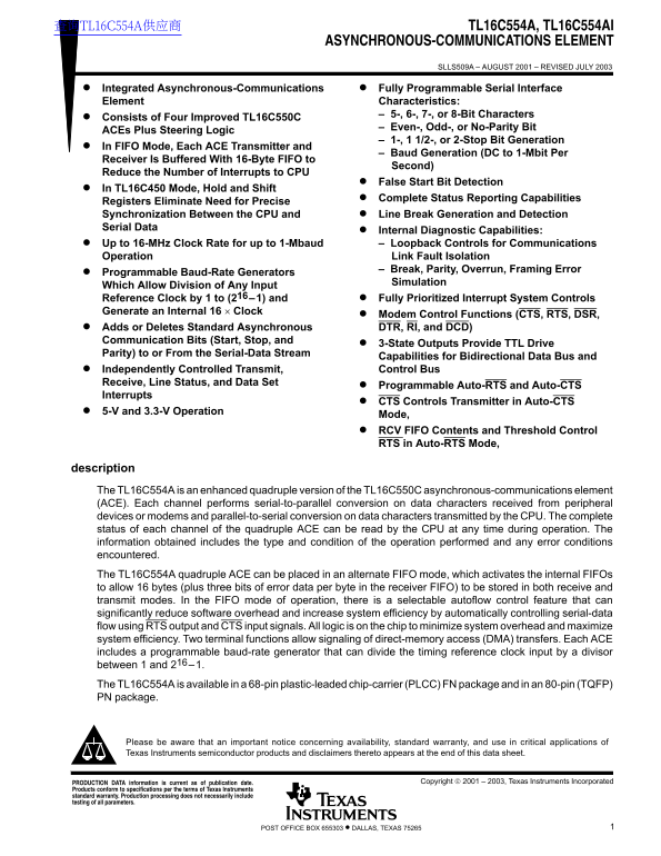
Integrated Asynchronous-Communications Fully Programmable Serial Interface Element Characteristics:

– 5-, 6-, 7-, or 8-Bit Characters

Consists of Four Improved TL16C550C

– Even-, Odd-, or No-Parity Bit

ACEs Plus Steering Logic

– 1-, 1 1/2-, or 2-Stop Bit Generation

In FIFO Mode, Each ACE Transmitter and

– Baud Generation (DC to 1-Mbit Per

Receiver Is Buffered With 16-Byte FIFO to

Second)

Reduce the Number of Interrupts to CPU

False Start Bit Detection

In TL16C450 Mode, Hold and Shift

Complete Status Reporting Capabilities

Registers Eliminate Need for Precise Synchronization Between the CPU and Line Break Generation and Detection Serial Data

Internal Diagnostic Capabilities: Up to 16-MHz Clock Rate for up to 1-Mbaud – Loopback Controls for Communications Operation Link Fault Isolation – Break, Parity, Overrun, Framing Error

Programmable Baud-Rate Generators

Simulation

Which Allow Division of Any Input Reference Clock by 1 to (216–1) and Fully Prioritized Interrupt System Controls Generate an Internal 16 × Clock

Modem Control Functions (CTS, RTS, DSR, Adds or Deletes Standard Asynchronous DTR, RI, and DCD)

Communication Bits (Start, Stop, and

3-State Outputs Provide TTL Drive

Parity) to or From the Serial-Data Stream

Capabilities for Bidirectional Data Bus and Independently Controlled Transmit, Control Bus

Receive, Line Status, and Data Set

Programmable Auto-RTS and Auto-CTS

Interrupts

CTS Controls Transmitter in Auto-CTS

5-V and 3.3-V Operation

Mode, RCV FIFO Contents and Threshold Control RTS in Auto-RTS Mode,

description The TL16C554A is an enhanced quadruple version of the TL16C550C asynchronous-communications element (ACE). Each channel performs serial-to-parallel conversion on data characters received from peripheral devices or modems and parallel-to-serial conversion on data characters transmitted by the CPU. The complete status of each channel of the quadruple ACE can be read by the CPU at any time during operation. The information obtained includes the type and condition of the operation performed and any error conditions encountered. The TL16C554A quadruple ACE can be placed in an alternate FIFO mode, which activates the internal FIFOs to allow 16 bytes (plus three bits of error data per byte in the receiver FIFO) to be stored in both receive and transmit modes. In the FIFO mode of operation, there is a selectable autoflow control feature that can significantly reduce software overhead and increase system efficiency by automatically controlling serial-data flow using RTS output and CTS input signals. All logic is on the chip to minimize system overhead and maximize system efficiency. Two terminal functions allow signaling of direct-memory access (DMA) transfers. Each ACE includes a programmable baud-rate generator that can divide the timing reference clock input by a divisor between 1 and 216–1. The TL16C554A is available in a 68-pin plastic-leaded chip-carrier (PLCC) FN package and in an 80-pin (TQFP) PN package.

Please be aware that an important notice concerning availability, standard warranty, and use in critical applications of Texas Instruments semiconductor products and disclaimers thereto appears at the end of this data sheet.

PRODUCTION DATA information is current as of publication date. Copyright  2001 – 2003, Texas Instruments Incorporated

Products conform to specifications per the terms of Texas Instruments standard warranty. Production processing does not necessarily include testing of all parameters.

1POST OFFICE BOX 655303 • DALLAS, TEXAS 75265

Page Summary Contents For Texas Instruments TL16C554A, TL16C554AI ASYNCHRONOUS-COMMUNICATIONS ELEMENT Data Handbook (1) Specification Sheet User Manual

Page 1 查询TL16C554A供应商 TL16C554A, TL16C554AI ASYNCHRONOUS-COMMUNICATIONS ELEMENT SLLS509A – AUGUST 2001 – REVISED JULY 2003 Integrated Asynchronous-Communications Fully Programmable Serial Interface Element C...
Page 2 TL16C554A, TL16C554AI ASYNCHRONOUS-COMMUNICATIONS ELEMENT SLLS509A – AUGUST 2001 – REVISED JULY 2003 FN PACKAGE (TOP VIEW) DSRA DSRD CTSA CTSD DTRA DTRD VCC GND RTSA RTSD IB IA INTA INTD CSA CSD TXA T...
Page 3 TL16C554A, TL16C554AI ASYNCHRONOUS-COMMUNICATIONS ELEMENT SLLS509A – AUGUST 2001 – REVISED JULY 2003 PN PACKAGE (TOP VIEW) NC NC DSRC DSRB CTSC CTSB ID IC DTRC DTRB VCC GND RTSC RTSB INTC INTB CSC CSB...
Page 4 TL16C554A, TL16C554AI ASYNCHRONOUS-COMMUNICATIONS ELEMENT SLLS509A – AUGUST 2001 – REVISED JULY 2003 functional block diagram (per channel) Internal Data Bus 5 – 66 Data Receiver D(7–0) Bus FIFO Buffe...
Page 5 TL16C554A, TL16C554AI ASYNCHRONOUS-COMMUNICATIONS ELEMENT SLLS509A – AUGUST 2001 – REVISED JULY 2003 Terminal Functions TERMINAL FN PN I/O DESCRIPTION NO. NO. A0 Register select terminals. A0, A1, and...
Page 6 TL16C554A, TL16C554AI ASYNCHRONOUS-COMMUNICATIONS ELEMENT SLLS509A – AUGUST 2001 – REVISED JULY 2003 Terminal Functions (Continued) TERMINAL FN PN I/O DESCRIPTION NO. NO. RXA, RXB 7, 29, 17, 44, Seria...
Page 7 TL16C554A, TL16C554AI ASYNCHRONOUS-COMMUNICATIONS ELEMENT SLLS509A – AUGUST 2001 – REVISED JULY 2003 recommended operating conditions, standard voltage (5 V-nominal) MIN NOM MAX UNIT Supply voltage, V...
Page 8 TL16C554A, TL16C554AI ASYNCHRONOUS-COMMUNICATIONS ELEMENT SLLS509A – AUGUST 2001 – REVISED JULY 2003 recommended operating conditions, low voltage (3.3-V nominal) MIN NOM MAX UNIT Supply voltage, VCC ...
Page 9 TL16C554A, TL16C554AI ASYNCHRONOUS-COMMUNICATIONS ELEMENT SLLS509A – AUGUST 2001 – REVISED JULY 2003 read cycle timing requirements over recommended ranges of operating free-air temperature and supply...
Page 10 TL16C554A, TL16C554AI ASYNCHRONOUS-COMMUNICATIONS ELEMENT SLLS509A – AUGUST 2001 – REVISED JULY 2003 transmitter switching characteristics over recommended ranges of operating free-air temperature and...
Page 11 TL16C554A, TL16C554AI ASYNCHRONOUS-COMMUNICATIONS ELEMENT SLLS509A – AUGUST 2001 – REVISED JULY 2003 PARAMETER MEASUREMENT INFORMATION Clock (XTAL1) fclock = 16 MHz MAX (a) CLOCK INPUT VOLTAGE WAVEFOR...
Page 12 TL16C554A, TL16C554AI ASYNCHRONOUS-COMMUNICATIONS ELEMENT SLLS509A – AUGUST 2001 – REVISED JULY 2003 PARAMETER MEASUREMENT INFORMATION 50% Valid A2, A1, A0 Valid CSx 50% 50% th2tsu1 Active Active IOR ...
Page 13 TL16C554A, TL16C554AI ASYNCHRONOUS-COMMUNICATIONS ELEMENT SLLS509A – AUGUST 2001 – REVISED JULY 2003 PARAMETER MEASUREMENT INFORMATION Start Start 50% Data (5–8) 50% TXx Stop (1–2) Parity td5 td6 INTx...
Page 14 TL16C554A, TL16C554AI ASYNCHRONOUS-COMMUNICATIONS ELEMENT SLLS509A – AUGUST 2001 – REVISED JULY 2003 PARAMETER MEASUREMENT INFORMATION TL16C450 Mode: SIN Data Bits (5–8) Parity Stop Start (receiver in...
Page 15 TL16C554A, TL16C554AI ASYNCHRONOUS-COMMUNICATIONS ELEMENT SLLS509A – AUGUST 2001 – REVISED JULY 2003 PARAMETER MEASUREMENT INFORMATION Sample Clock td9 (see Note A) (FIFO at or above trigger level) (t...
Page 16 TL16C554A, TL16C554AI ASYNCHRONOUS-COMMUNICATIONS ELEMENT SLLS509A – AUGUST 2001 – REVISED JULY 2003 PARAMETER MEASUREMENT INFORMATION NOTES: A. This is the reading of the last byte in the FIFO. B. If...
Page 17 TL16C554A, TL16C554AI ASYNCHRONOUS-COMMUNICATIONS ELEMENT SLLS509A – AUGUST 2001 – REVISED JULY 2003 tpd10 TXx 50% Midpoint of Stop Bit Figure 15. CTS and TX Autoflow Control Timing (Start and Stop) W...
Page 18 TL16C554A, TL16C554AI ASYNCHRONOUS-COMMUNICATIONS ELEMENT SLLS509A – AUGUST 2001 – REVISED JULY 2003 PRINCIPLES OF OPERATION Three types of information are stored in the internal registers used in the...
Page 19 TL16C554A, TL16C554AI ASYNCHRONOUS-COMMUNICATIONS ELEMENT SLLS509A – AUGUST 2001 – REVISED JULY 2003 PRINCIPLES OF OPERATION accessible registers The system programmer, using the CPU, has access to an...
Page 20 TL16C554A, TL16C554AI ASYNCHRONOUS-COMMUNICATIONS ELEMENT SLLS509A – AUGUST 2001 – REVISED JULY 2003 PRINCIPLES OF OPERATION FIFO-control register (FCR) The FCR is a write-only register at the same lo...
Page 21 TL16C554A, TL16C554AI ASYNCHRONOUS-COMMUNICATIONS ELEMENT SLLS509A – AUGUST 2001 – REVISED JULY 2003 PRINCIPLES OF OPERATION FIFO interrupt mode operation (continued) The following receiver FIFO chara...
Page 22 TL16C554A, TL16C554AI ASYNCHRONOUS-COMMUNICATIONS ELEMENT SLLS509A – AUGUST 2001 – REVISED JULY 2003 PRINCIPLES OF OPERATION interrupt-enable register (IER) The IER independently enables the four seri...
Page 23 TL16C554A, TL16C554AI ASYNCHRONOUS-COMMUNICATIONS ELEMENT SLLS509A – AUGUST 2001 – REVISED JULY 2003 PRINCIPLES OF OPERATION interrupt-identification register (IIR) (continued) Bit 0: IIR0 indicates w...
Page 24 TL16C554A, TL16C554AI ASYNCHRONOUS-COMMUNICATIONS ELEMENT SLLS509A – AUGUST 2001 – REVISED JULY 2003 PRINCIPLES OF OPERATION line-control register (LCR) (continued) LINE CONTROL REGISTER LCR LCR LCR L...
Page 25 TL16C554A, TL16C554AI ASYNCHRONOUS-COMMUNICATIONS ELEMENT SLLS509A – AUGUST 2001 – REVISED JULY 2003 PRINCIPLES OF OPERATION line-status register (LSR) (continued) Bit 4: LSR4 is the break interrupt (...
Page 26 TL16C554A, TL16C554AI ASYNCHRONOUS-COMMUNICATIONS ELEMENT SLLS509A – AUGUST 2001 – REVISED JULY 2003 PRINCIPLES OF OPERATION modem-control register (MCR) The MCR controls the interface with the modem ...
Page 27 TL16C554A, TL16C554AI ASYNCHRONOUS-COMMUNICATIONS ELEMENT SLLS509A – AUGUST 2001 – REVISED JULY 2003 modem-control register (MCR) (continued) Bit 6 – Bit 7: MCR5, MCR6, and MCR7 are permanently cleare...
Page 28 TL16C554A, TL16C554AI ASYNCHRONOUS-COMMUNICATIONS ELEMENT SLLS509A – AUGUST 2001 – REVISED JULY 2003 PRINCIPLES OF OPERATION modem-status register (MSR) (continued) Bit 6: MSR6 is the ring indicator (...
Page 29 TL16C554A, TL16C554AI ASYNCHRONOUS-COMMUNICATIONS ELEMENT SLLS509A – AUGUST 2001 – REVISED JULY 2003 PRINCIPLES OF OPERATION programmable baud-rate generator (continued) Table 9. Baud Rates Using a 1....
Page 30 TL16C554A, TL16C554AI ASYNCHRONOUS-COMMUNICATIONS ELEMENT SLLS509A – AUGUST 2001 – REVISED JULY 2003 PRINCIPLES OF OPERATION programmable baud-rate generator (continued) Table 11. Baud Rates Using an ...
Page 31 TL16C554A, TL16C554AI ASYNCHRONOUS-COMMUNICATIONS ELEMENT SLLS509A – AUGUST 2001 – REVISED JULY 2003 Table 12. Baud Rates Using an 16-MHz Clock BAUD RATE DIVISOR (N) USED TO PERCENT ERROR DIFFERENCE D...
Page 32 TL16C554A, TL16C554AI ASYNCHRONOUS-COMMUNICATIONS ELEMENT SLLS509A – AUGUST 2001 – REVISED JULY 2003 PRINCIPLES OF OPERATION autoflow control (see Figure 20) Autoflow control is comprised of auto-CTS ...
Page 33 TL16C554A, TL16C554AI ASYNCHRONOUS-COMMUNICATIONS ELEMENT SLLS509A – AUGUST 2001 – REVISED JULY 2003 PRINCIPLES OF OPERATION auto-CTS and auto-RTS functional timing Start Bits 0–7 Start Bits 0–7 Stop ...
Page 34 TL16C554A, TL16C554AI ASYNCHRONOUS-COMMUNICATIONS ELEMENT SLLS509A – AUGUST 2001 – REVISED JULY 2003 PRINCIPLES OF OPERATION reset After power up, the ACE RESET input should be held high for one micro...
Page 35 TL16C554A, TL16C554AI ASYNCHRONOUS-COMMUNICATIONS ELEMENT SLLS509A – AUGUST 2001 – REVISED JULY 2003 PRINCIPLES OF OPERATION scratchpad register The scratchpad register is an 8-bit read/write register...
Page 36 TL16C554A, TL16C554AI ASYNCHRONOUS-COMMUNICATIONS ELEMENT SLLS509A – AUGUST 2001 – REVISED JULY 2003 MECHANICAL DATA FN (S-PQCC-J**) PLASTIC J-LEADED CHIP CARRIER 20 PIN SHOWN Seating Plane 0.004 (0,1...
Page 37 TL16C554A, TL16C554AI ASYNCHRONOUS-COMMUNICATIONS ELEMENT SLLS509A – AUGUST 2001 – REVISED JULY 2003 MECHANICAL DATA PN (S-PQFP-G80) PLASTIC QUAD FLATPACK 0,13 NOM Gage Plane 9,50 TYP 11,80 0,05 MIN 0...
Page 38 MECHANICAL DATA MPLC004A – OCTOBER 1994 FN (S-PQCC-J**) PLASTIC J-LEADED CHIP CARRIER 20 PIN SHOWN Seating Plane 0.004 (0,10) 0.180 (4,57) MAX 0.120 (3,05) D1 0.090 (2,29) 0.020 (0,51) MIN 0.008 (0,20...
Page 39 MECHANICAL DATA MTQF010A – JANUARY 1995 – REVISED DECEMBER 1996 PN (S-PQFP-G80) PLASTIC QUAD FLATPACK 0,13 NOM Gage Plane 9,50 TYP 11,80 0,05 MIN 0°–7° 14,20 SQ 13,80 Seating Plane 1,60 MAX 0,08 NOTES...
Page 40 IMPORTANT NOTICE Texas Instruments Incorporated and its subsidiaries (TI) reserve the right to make corrections, modifications, enhancements, improvements, and other changes to its products and servic...

Manual Details

Brand Texas Instruments
Pages 40
File Size 580.53 KB
Published June 06, 2026
47 views

Enter the captcha to get the download link:

captcha

Frequently Asked Questions

What are the available package options for the TL16C554A?

The device is available in a 68-pin plastic-leaded chip-carrier (PLCC) FN package and an 80-pin (TQFP) PN package.

How does FIFO Mode improve system efficiency?

In FIFO mode, internal FIFOs store up to 16 bytes for both receive and transmit modes. It also includes a selectable autoflow control feature that reduces software overhead.

What is the maximum operating clock rate of this element?

It supports up to a 16-MHz Clock Rate for up to 1-Mbaud communication.

Does the device support direct memory access (DMA)?

Yes, two terminal functions allow signaling of direct-memory access (DMA) transfers.

What types of communications line faults can be detected?

Loopback controls provide isolation for common errors including Break, Parity, Overrun, and Framing Error.