Texas Instruments SN5414, SN54LS14, SN7414, SN74LS14 Hex Schmitt-Trigger Inverters Data Sheet User Manual
Summary
These datasheets provide comprehensive specifications for SN5414, SN54LS14, and related series of HEX Schmitt-Trigger Inverters. The manual details key electrical parameters, operational thresholds for positive and negative signals, and temperature compensation features. Ideal for electronics engineers and hardware designers, this guide helps implement clean, jitter-free signal conditioning in digital circuits, covering multiple packages and ordering variations for reliable component selection.
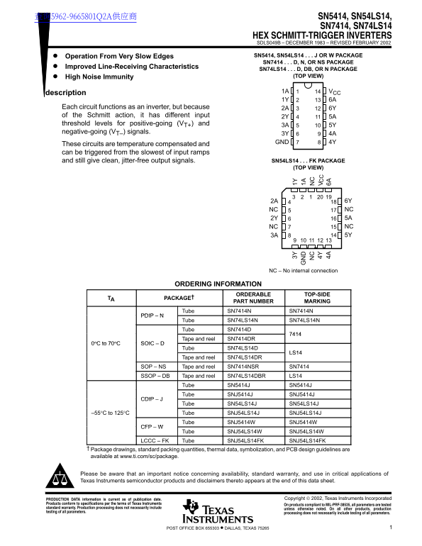
Page 1 Text Content
查询5962-9665801Q2A供应商 SN5414, SN54LS14,
SN7414, SN74LS14
HEX SCHMITT-TRIGGER INVERTERS SDLS049B – DECEMBER 1983 – REVISED FEBRUARY 2002 Operation From Very Slow Edges SN5414, SN54LS14 J OR W PACKAGE SN7414 D, N, OR NS PACKAGE
Improved Line-Receiving Characteristics
SN74LS14 D, DB, OR N PACKAGE
High Noise Immunity (TOP VIEW)
description 1A VCC
Each circuit functions as an inverter, but because 2A 6Y of the Schmitt action, it has different input 2Y 5A threshold levels for positive-going (VT+) and
negative-going (VT–) signals.
3Y 4A GND 4Y
These circuits are temperature compensated and can be triggered from the slowest of input ramps and still give clean, jitter-free output signals. SN54LS14 FK PACKAGE
(TOP VIEW)
2A 6Y NC NC 2Y 5A NC NC 3A 5Y
NC – No internal connection
ORDERING INFORMATION
ORDERABLE 3Y TOP-SIDE 1Y
TA PACKAGE†
PART NUMBER MARKING
Tube SN7414N SN7414N
Tube SN74LS14N 4Y SN74LS14N Tube SN7414D 4A 6A
Tape and reel SN7414DR
0°C to 70°C SOIC
Tube SN74LS14D
Tape and reel SN74LS14DR
SOP – NS Tape and reel SN7414NSR SN7414 SSOP – DB Tape and reel SN74LS14DBR LS14
Tube SN5414J SN5414J Tube SNJ5414J SNJ5414J
Tube SN54LS14J SN54LS14J
–55°C to 125°C Tube SNJ54LS14J SNJ54LS14J
Tube SNJ5414W SNJ5414W
Tube SNJ54LS14W SNJ54LS14W
LCCC – FK Tube SNJ54LS14FK SNJ54LS14FK
Package drawings, standard packing quantities, thermal data, symbolization, and PCB design guidelines are available at www.ti.com/sc/package.
Please be aware that an important notice concerning availability, standard warranty, and use in critical applications of Texas Instruments semiconductor products and disclaimers thereto appears at the end of this data sheet.
Copyright 2002, Texas Instruments Incorporated PRODUCTION DATA information is current as of publication date.
Products conform to specifications per the terms of Texas Instruments On products compliant to MIL-PRF-38535, all parameters are tested standard warranty. Production processing does not necessarily include unless otherwise noted. On all other products, production testing of all parameters. processing does not necessarily include testing of all parameters.
1POST OFFICE BOX 655303 • DALLAS, TEXAS 75265
Page Summary Contents For Texas Instruments SN5414, SN54LS14, SN7414, SN74LS14 Hex Schmitt-Trigger Inverters Data Sheet User Manual
Manual Details
| Brand | Texas Instruments |
|---|---|
| Pages | 22 |
| File Size | 592.77 KB |
| Published | June 06, 2026 |
Enter the captcha to get the download link:

Frequently Asked Questions
What is the primary benefit of using Schmitt action on these inverters?
Schmitt action provides different input threshold levels for positive and negative signals, ensuring clean, jitter-free output.
Where can I find package drawings and PCB design guidelines?
Package drawings and standard packing quantities are available at www.ti.com/sc/package.
What is the recommended supply voltage (VCC) range for these devices?
For the SN7414, VCC must be less than 5.5V; for SN74LS14, it must be less than 7V.