# A B C D E F G H I J K L M N O P Q R S T U V W X Y Z

Texas Instruments PCM1748 Data Sheet/Manual

Summary

This integrated circuit is a premium 24-Bit Digital-to-Analog Converter (DAC) engineered for superior audio fidelity. The accompanying documentation provides detailed technical specifications, coverage, and applications needed to integrate this advanced component into high-end consumer and professional equipment. It is primarily designed for use in markets such as HDTV receivers, DVD players, multichannel audio systems, and specialized car audio units requiring high resolution and up to 96kHz sampling rates.
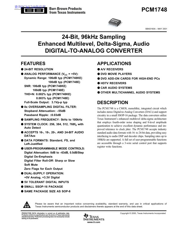
📄 Preview PAGE OF 22

Page 1 Text Content

查询PCM1748供应商

PCM1748

PCM1748

SBAS165A – MAY 2001

24-Bit, 96k Hz Sampling

Enhanced Multilevel, Delta-Sigma, Audio DIGITAL-TO-ANALOG CONVERTER

FEATURES APPLICATIONS 24-BIT RESOLUTION A/V RECEIVERS ANALOG PERFORMANCE (VCC = +5V): DVD MOVIE PLAYERS Dynamic Range: 106d B typ (PCM1748KE) DVD ADD-ON CARDS FOR HIGH-END PCs

100d B typ (PCM1748E)

HDTV RECEIVERS

SNR: 106d B typ (PCM1748KE)

CAR AUDIO SYSTEMS

100d B typ (PCM1748E)

OTHER MULTICHANNEL AUDIO SYSTEMS

THD+N: 0.002% typ (PCM1748KE)

0.003% typ (PCM1748E)

Full-Scale Output: 3.1Vp-p typ DESCRIPTION 8x OVERSAMPLING DIGITAL FILTER:

The PCM1748 is a CMOS, monolithic, integrated circuit which

Stopband Attenuation: –55d B

includes stereo Digital-to-Analog Converters (DACs) and support

Passband Ripple: ±0.03d B circuitry in a small SSOP-16 package. The data converters utilize

Texas Instrument’s enhanced multilevel delta-sigma architecture

SAMPLING FREQUENCY: 5k Hz to 100k Hz

that employs fourth-order noise shaping and 8-level amplitude

SYSTEM CLOCK: 256, 384, 512, 768f S with

quantization to achieve excellent dynamic performance and im-

Auto Detect

proved tolerance to clock jitter. The PCM1748 accepts industry

ACCEPTS 16-, 18-, 20-, AND 24-BIT AUDIO standard audio data formats with 16- to 24-bit data, providing easy DATAzx interfacing to audio DSP and decoder chips. Sampling rates up to

100k Hz are supported. A full set of user-programmable functions

DATA FORMATS: Standard, I2S, and

are accessible through a 3-wire serial control port that supports

Left-Justified

register write functions.

USER-PROGRAMMABLE MODE CONTROLS: Digital Attenuation: 0d B to –63d B, 0.5d B/Step Digital De-Emphasis Digital Filter Roll-Off: Sharp or Slow Soft Mute Zero Flags for Each Output DUAL-SUPPLY OPERATION: +5V Analog, +3.3V Digital 5V TOLERANT DIGITAL INPUTS SMALL SSOP-16 PACKAGE SAME PACKAGE SIZE AS SOP-8

Please be aware that an important notice concerning availability, standard warranty, and use in critical applications of Texas Instruments semiconductor products and disclaimers thereto appears at the end of this data sheet.

PRODUCTION DATA information is current as of publication date. Copyright © 2000, Texas Instruments Incorporated Products conform to specifications per the terms of Texas Instruments standard warranty. Production processing does not necessarily include testing of all parameters.

www.ti.com

Page Summary Contents For Texas Instruments PCM1748 Data Sheet/Manual

Page 1 查询PCM1748供应商 PCM1748 PCM1748 SBAS165A – MAY 2001 24-Bit, 96k Hz Sampling Enhanced Multilevel, Delta-Sigma, Audio DIGITAL-TO-ANALOG CONVERTER FEATURES APPLICATIONS 24-BIT RESOLUTION A/V RECEIVERS ANALO...
Page 2 ABSOLUTE MAXIMUM RATINGS ELECTROSTATIC Power Supply Voltage, VDD +4.0V VCC +6.5V DISCHARGE SENSITIVITY Ground Voltage Differences ±0.1V This integrated circuit can be damaged by ESD. Texas Instru- Dig...
Page 3 ELECTRICAL CHARACTERISTICS All specifications at TA = +25°C, VCC = 5.0V, VDD = 3.3V, f S = 44.1k Hz, system clock = 384f S, and 24-bit data, unless otherwise noted. PCM1748E PCM1748KE PARAMETER CONDIT...
Page 4 ELECTRICAL CHARACTERISTICS (Cont.) All specifications at TA = +25°C, VCC = 5.0V, VDD = 3.3V, system clock = 384f S (f S = 44.1k Hz), and 24-bit data, unless otherwise noted. PCM1748E PCM1748KE PARAMET...
Page 5 TYPICAL CHARACTERISTICS All specifications at TA = +25°C, VCC = 5.0V, VDD = 3.3V, system clock = 384f S (f S = 44.1k Hz), and 24-bit input data, unless otherwise noted. DIGITAL FILTER Digital Filter (...
Page 6 TYPICAL CHARACTERISTICS (Cont.) Le ve l ( d B Le ve l ( d B All specifications at TA = +25°C, VCC = 5.0V, VDD = 3.3V, system clock = 384f S (f S = 44.1k Hz), and 24-bit input data, unless otherwise no...
Page 7 TYPICAL CHARACTERISTICS (Cont.) All specifications at TA = +25°C, VCC = 5.0V, VDD = 3.3V, and 24-bit input data, unless otherwise noted. Supply-Voltage Characteristics (Cont.) SNR vs VCC (VDD = 3.3V) ...
Page 8 SYSTEM CLOCK AND RESET POWER-ON RESET FUNCTIONS The PCM1748 includes a power-on reset function, as shown in FUNCTIONS Figure 2. With the system clock active, and VDD > 2.0V (typical SYSTEM CLOCK IN...
Page 9 AUDIO SERIAL INTERFACE clock of LRCK is changed or SCK and/or BCK is broken at least for one clock cycle. If SCK, BCK, and LRCK are The audio serial interface for the PCM1748 is comprised of provided ...
Page 10 LRCK 50% of VDD t BCH t BCL t LB BCK 50% of VDD t BCY t BL DATA 50% of VDD t DS t DH SYMBOL PARAMETER MIN MAX UNITS t BCY BCK Pulse Cycle Time 32, 48, or 64f S(1) t BCH BCK High Level Time ns t BCL BC...
Page 11 MODE CONTROL REGISTERS available mode control functions, along with their reset default conditions and associated register index. User-Programmable Mode Controls Register Map The PCM1748 includes a nu...
Page 12 REGISTER DEFINITIONS Register 16 IDX6 IDX5 IDX4 IDX3 IDX2 IDX1 IDX0 AT17 AT16 AT15 AT14 AT13 AT12 AT11 AT10 Register 17 IDX6 IDX5 IDX4 IDX3 IDX2 IDX1 IDX0 AT27 AT26 AT25 AT24 AT23 AT22 AT21 AT20 ATx[7...
Page 13 REGISTER 19 IDX6 IDX5 IDX4 IDX3 IDX2 IDX1 IDX0 RSV DMF1 DMF0 DM12 RSV RSV DAC2 DAC1 DACx DAC Operation Control where x = 1 or 2, corresponding to the DAC output VOUTL (x = 1) or VOUTR (x = 2). Default...
Page 14 Register 20 (Cont.) FLT Digital Filter Roll-Off Control Default Value: 0 FLT = 0 Sharp Roll-Off (default) FLT = 1 Slow Roll-Off The FLT bit allows the user to select the digital filter roll-off that i...
Page 15 ANALOG OUTPUTS enough to attenuate the out-of-band noise to an acceptable level for many applications, therefore, an external low-pass The PCM1748 includes two independent output channels: filter is r...
Page 16 to operate external mute circuits, or used as status indicators Power Supplies and Grounding for a microcontroller, audio signal processor, or other digitally The PCM1748 requires a +5V analog supply ...
Page 17 PCB LAYOUT GUIDELINES Separate power supplies are recommended for the digital and analog sections of the board. This prevents the switching noise A typical PCB floor plan for the PCM1748 is shown in p...
Page 18 THEORY OF OPERATION one-bit (2-level) delta-sigma modulator. The combined oversampling rate of the delta-sigma modulator and the interpo- The delta-sigma section of the PCM1748 is based on an lation f...
Page 19 Total Harmonic Distortion + Noise JITTER DEPENDENCE (64x Oversampling) Total Harmonic Distortion + Noise (THD+N) is a significant figure of merit for audio DACs, since it takes into account both harmo...
Page 20 Dynamic Range Idle Channel Signal-to-Noise Ratio Dynamic range is specified as A-Weighted, THD+N mea- The SNR test provides a measure of the noise floor of the sured with a –60d BFS, 1k Hz digital sin...
Page 21 PACKAGE OPTION ADDENDUM www.ti.com 21-Dec-2004 PACKAGING INFORMATION Orderable Device Status Package Package Pins Package Eco Plan Lead/Ball Finish MSL Peak Temp Type Drawing Qty PCM1748E ACTIVE SSOP/...
Page 22 IMPORTANT NOTICE Texas Instruments Incorporated and its subsidiaries (TI) reserve the right to make corrections, modifications, enhancements, improvements, and other changes to its products and servic...

Manual Details

Brand Texas Instruments
Pages 22
File Size 317.42 KB
Published June 18, 2026
1 views

Enter the captcha to get the download link:

captcha

Frequently Asked Questions

What bit depths of audio data does the PCM1748 support?

It accepts standard audio data formats ranging from 16-bit up to 24-bit.

What power supplies are required for operation?

The module operates using a dual-supply system: +5V for Analog and +3.3V for Digital.

What is the maximum supported sampling frequency?

Sampling rates of up to 100kHz are supported by this device.

Are there specific handling requirements?

Be aware that the integrated circuit can be damaged by ESD, so proper anti-static precautions are essential.