# A B C D E F G H I J K L M N O P Q R S T U V W X Y Z

Texas Instruments MSP430x31x User's Manual

Summary

The MSP430 combines 16-bit RISC architecture with integrated mixed-signal capabilities, making it the ideal choice for extended battery-powered applications. Engineered for ultralow power consumption, this microcontroller excels in handling complex sensor systems by managing analog data conversion and digital processing. This technical manual provides comprehensive details on the device's various models, I/O configurations, power-saving modes, and specialized features like A/D conversion and LCD driving, serving as a crucial resource for embedded system designers.
📄 Preview PAGE OF 30

Page 1 Text Content

MSP430x31x

MIXED SIGNAL MICROCONTROLLERS SLAS165D – FEBRUARY 1998 – REVISED APRIL 2000

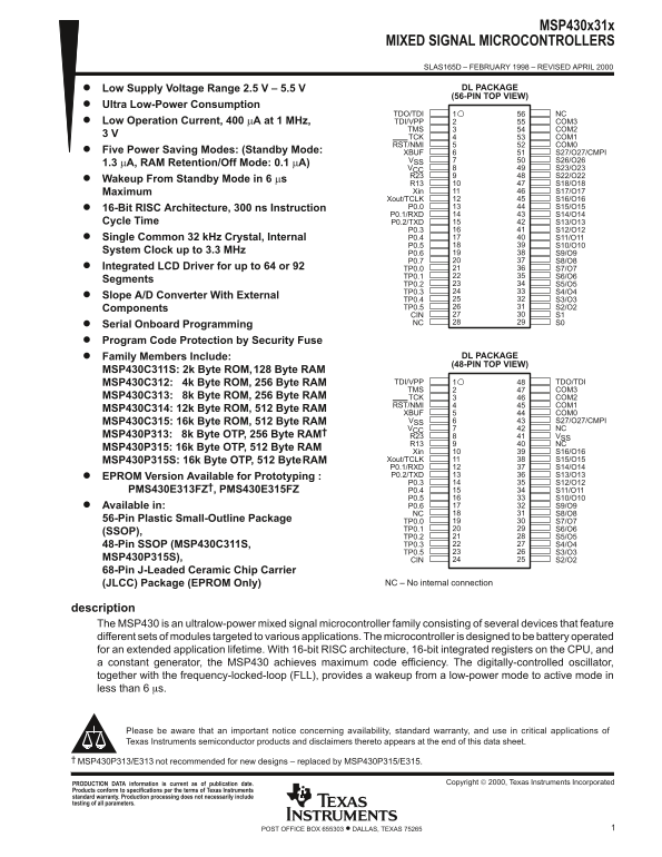
Low Supply Voltage Range 2.5 V – 5.5 V DL PACKAGE (56-PIN TOP VIEW)

Ultra Low-Power Consumption

TDO/TDI NC

Low Operation Current, 400 µA at 1 MHz, TDI/VPP COM3

TMS COM2 TCK COM1 RST/NMI COM0

Five Power Saving Modes: (Standby Mode: XBUF S27/O27/CMPI

VSS S26/O26

1.3 µA, RAM Retention/Off Mode: 0.1 µA)

VCC S23/O23 R23 S22/O22

Wakeup From Standby Mode in 6 µs

R13 S18/O18 Maximum Xin S17/O17 Xout/TCLK S16/O16 16-Bit RISC Architecture, 300 ns Instruction P0.0 S15/O15 P0.1/RXD S14/O14

Cycle Time P0.2/TXD S13/O13

P0.3 S12/O12 Single Common 32 k Hz Crystal, Internal P0.4 S11/O11 P0.5 S10/O10

System Clock up to 3.3 MHz

Integrated LCD Driver for up to 64 or 92 TP0.0 S7/O7

TP0.1 S6/O6

Segments

TP0.2 S5/O5 TP0.3 S4/O4

Slope A/D Converter With External

TP0.4 S3/O3 Components TP0.5 S2/O2 CIN S1 Serial Onboard Programming NC S0

Program Code Protection by Security Fuse

Family Members Include: DL PACKAGE (48-PIN TOP VIEW)

MSP430C311S: 2k Byte ROM,128 Byte RAM

MSP430C312: 4k Byte ROM, 256 Byte RAM TDI/VPP TDO/TDI TMS COM3

MSP430C313: 8k Byte ROM, 256 Byte RAM TCK COM2

RST/NMI COM1

MSP430C314: 12k Byte ROM, 512 Byte RAM

XBUF COM0 MSP430C315: 16k Byte ROM, 512 Byte RAM VSS S27/O27/CMPI VCC NC

MSP430P313: 8k Byte OTP, 256 Byte RAM† R23 VSS

R13 NC

MSP430P315: 16k Byte OTP, 512 Byte RAM

Xin S16/O16 MSP430P315S: 16k Byte OTP, 512 Byte RAM Xout/TCLK S15/O15 P0.1/RXD S14/O14 EPROM Version Available for Prototyping : P0.2/TXD S13/O13 P0.3 S12/O12

PMS430E313FZ†, PMS430E315FZ P0.4 S11/O11

P0.5 S10/O10 Available in: P0.6 S9/O9 NC S8/O8

56-Pin Plastic Small-Outline Package TP0.0 S7/O7

TP0.1 S6/O6

(SSOP),

TP0.2 S5/O5 48-Pin SSOP (MSP430C311S, TP0.3 S4/O4 TP0.5 S3/O3

MSP430P315S), CIN S2/O2 68-Pin J-Leaded Ceramic Chip Carrier

(JLCC) Package (EPROM Only) NC – No internal connection

description The MSP430 is an ultralow-power mixed signal microcontroller family consisting of several devices that feature different sets of modules targeted to various applications. The microcontroller is designed to be battery operated for an extended application lifetime. With 16-bit RISC architecture, 16-bit integrated registers on the CPU, and a constant generator, the MSP430 achieves maximum code efficiency. The digitally-controlled oscillator, together with the frequency-locked-loop (FLL), provides a wakeup from a low-power mode to active mode in less than 6 s.

Please be aware that an important notice concerning availability, standard warranty, and use in critical applications of Texas Instruments semiconductor products and disclaimers thereto appears at the end of this data sheet.

MSP430P313/E313 not recommended for new designs – replaced by MSP430P315/E315.

Copyright  2000, Texas Instruments Incorporated PRODUCTION DATA information is current as of publication date.

Products conform to specifications per the terms of Texas Instruments standard warranty. Production processing does not necessarily include testing of all parameters.

1POST OFFICE BOX 655303 • DALLAS, TEXAS 75265

Page Summary Contents For Texas Instruments MSP430x31x User's Manual

Page 1 MSP430x31x MIXED SIGNAL MICROCONTROLLERS SLAS165D – FEBRUARY 1998 – REVISED APRIL 2000 Low Supply Voltage Range 2.5 V – 5.5 V DL PACKAGE (56-PIN TOP VIEW) Ultra Low-Power Consumption TDO/TDI NC Low Op...
Page 2 MSP430x31x MIXED SIGNAL MICROCONTROLLERS SLAS165D – FEBRUARY 1998 – REVISED APRIL 2000 description (continued) Typical applications include sensor systems that capture analog signals, converting them ...
Page 3 MSP430x31x MIXED SIGNAL MICROCONTROLLERS SLAS165D – FEBRUARY 1998 – REVISED APRIL 2000 Terminal Functions MSP430C312, MSP430C313†, MSP430C314, MSP430C315, MSP430P313†, MSP430P315 56-pin SSOP package T...
Page 4 MSP430x31x MIXED SIGNAL MICROCONTROLLERS SLAS165D – FEBRUARY 1998 – REVISED APRIL 2000 functional block diagram MSP430C311S and MSP430P315S VCC VSS XIN Xout XBUF RST/NMI P0.1–6 Oscillator ACLK ROM 128...
Page 5 MSP430x31x MIXED SIGNAL MICROCONTROLLERS SLAS165D – FEBRUARY 1998 – REVISED APRIL 2000 Terminal Functions MSP430C311S, MSP430P315S 48-pin SSOP package TERMINAL I/O DESCRIPTION NAME NO. CIN Counter ena...
Page 6 MSP430x31x MIXED SIGNAL MICROCONTROLLERS SLAS165D – FEBRUARY 1998 – REVISED APRIL 2000 short-form description processing unit The processing unit is based on a consistent and orthogonal designed CPU a...
Page 7 MSP430x31x MIXED SIGNAL MICROCONTROLLERS SLAS165D – FEBRUARY 1998 – REVISED APRIL 2000 Table 2. Address Mode Descriptions ADDRESS MODE SYNTAX EXAMPLE OPERATION Register MOV Rs, Rd MOV R10, R11 R10 → R...
Page 8 MSP430x31x MIXED SIGNAL MICROCONTROLLERS SLAS165D – FEBRUARY 1998 – REVISED APRIL 2000 operation modes and interrupts (continued) The most general bits that influence current consumption and support f...
Page 9 MSP430x31x MIXED SIGNAL MICROCONTROLLERS SLAS165D – FEBRUARY 1998 – REVISED APRIL 2000 special function registers Most interrupt and module enable bits are collected into the lowest address space. Spe...
Page 10 MSP430x31x MIXED SIGNAL MICROCONTROLLERS SLAS165D – FEBRUARY 1998 – REVISED APRIL 2000 memory organization MSP430C311S MSP430C312 MSP430C313 MSP430C314 MSP430C315 FFFFh FFFFh FFFFh FFFFh FFFFh Int. Ve...
Page 11 MSP430x31x MIXED SIGNAL MICROCONTROLLERS SLAS165D – FEBRUARY 1998 – REVISED APRIL 2000 peripherals Peripherals connected to the CPU through a data, address, and control busses can be handled easily wi...
Page 12 MSP430x31x MIXED SIGNAL MICROCONTROLLERS SLAS165D – FEBRUARY 1998 – REVISED APRIL 2000 peripherals (continued) digital I/O There is one eight-bit I/O port, Port0, that is implemented (MSP430C311S and ...
Page 13 MSP430x31x MIXED SIGNAL MICROCONTROLLERS SLAS165D – FEBRUARY 1998 – REVISED APRIL 2000 peripherals (continued) slope A/D conversion Slope A/D conversion is accomplished with the timer/port module usin...
Page 14 MSP430x31x MIXED SIGNAL MICROCONTROLLERS SLAS165D – FEBRUARY 1998 – REVISED APRIL 2000 8-Bit Timer/Counter (continued) Two counter inputs (load, enable) control the counter operation. The load input c...
Page 15 MSP430x31x MIXED SIGNAL MICROCONTROLLERS SLAS165D – FEBRUARY 1998 – REVISED APRIL 2000 absolute maximum ratings† Voltage applied at VCC to VSS –0.3 V to 6 V. . . . . . . . . . . . . . . . . . . . . . ...
Page 16 MSP430x31x MIXED SIGNAL MICROCONTROLLERS SLAS165D – FEBRUARY 1998 – REVISED APRIL 2000 f(MHz) sy st em ax im ro ce ss Minimum re en cy 2.7 5.5 VCC (V) VCC – Supply Voltage – V NOTE: Minimum processor ...
Page 17 MSP430x31x MIXED SIGNAL MICROCONTROLLERS SLAS165D – FEBRUARY 1998 – REVISED APRIL 2000 electrical characteristics over recommended operating free-air temperature range (unless otherwise noted) (contin...
Page 18 MSP430x31x MIXED SIGNAL MICROCONTROLLERS SLAS165D – FEBRUARY 1998 – REVISED APRIL 2000 electrical characteristics over recommended operating free-air temperature range (unless otherwise noted) (contin...
Page 19 MSP430x31x MIXED SIGNAL MICROCONTROLLERS SLAS165D – FEBRUARY 1998 – REVISED APRIL 2000 electrical characteristics over recommended and operating free-air temperature range (unless otherwise noted) (co...
Page 20 MSP430x31x MIXED SIGNAL MICROCONTROLLERS SLAS165D – FEBRUARY 1998 – REVISED APRIL 2000 electrical characteristics over recommended operating free-air temperature range (unless otherwise noted) LCD PAR...
Page 21 MSP430x31x MIXED SIGNAL MICROCONTROLLERS SLAS165D – FEBRUARY 1998 – REVISED APRIL 2000 (POR) No POR POR POR (min) Figure 4. Power-On Reset (POR) vs Supply Voltage Temperature [°C] Figure 5. V(POR) vs ...
Page 22 MSP430x31x MIXED SIGNAL MICROCONTROLLERS SLAS165D – FEBRUARY 1998 – REVISED APRIL 2000 electrical characteristics over recommended operating free-air temperature range (unless otherwise noted) JTAG, p...
Page 23 MSP430x31x MIXED SIGNAL MICROCONTROLLERS SLAS165D – FEBRUARY 1998 – REVISED APRIL 2000 TYPICAL CHARACTERISTICS JTAG fuse check mode MSP430 devices that have the fuse on the TDI/VPP terminal have a fus...
Page 24 MSP430x31x MIXED SIGNAL MICROCONTROLLERS SLAS165D – FEBRUARY 1998 – REVISED APRIL 2000 TYPICAL CHARACTERISTICS DIGITAL CONTROLLED OSCILLATOR FREQUENCY DIGITAL CONTROLLED OSCILLATOR FREQUENCY vs vs OPE...
Page 25 MSP430x31x MIXED SIGNAL MICROCONTROLLERS SLAS165D – FEBRUARY 1998 – REVISED APRIL 2000 TYPICAL CHARACTERISTICS typical input/output schematics VCC VCC (see Note A) (see Note A) (see Note B) (see Note ...
Page 26 MSP430x31x MIXED SIGNAL MICROCONTROLLERS SLAS165D – FEBRUARY 1998 – REVISED APRIL 2000 TYPICAL CHARACTERISTICS typical input/output schematics COM0–3 Control COM0–3 Segment control S2/O2–Sn/On Segment...
Page 27 MSP430x31x MIXED SIGNAL MICROCONTROLLERS SLAS165D – FEBRUARY 1998 – REVISED APRIL 2000 MECHANICAL DATA DL (R-PDSO-G**) PLASTIC SMALL-OUTLINE PACKAGE 48-PIN SHOWN 0.006 (0,15) NOM 0.420 (10,67) 0.395 (...
Page 28 MSP430x31x MIXED SIGNAL MICROCONTROLLERS SLAS165D – FEBRUARY 1998 – REVISED APRIL 2000 PMS430E313†, PMS430E315 (FZ package) FZ PACKAGE (TOP VIEW) NC NC NC S23/O23 VCC S22/O22 Xin S16/O16 Xout/TCLK S15...
Page 29 MSP430x31x MIXED SIGNAL MICROCONTROLLERS SLAS165D – FEBRUARY 1998 – REVISED APRIL 2000 MECHANICAL DATA FZ (S-CQCC-J**) J-LEADED CERAMIC CHIP CARRIER 28 LEAD SHOWN 0.040 (1,02) 45° Seating Plane (at ...
Page 30 IMPORTANT NOTICE Texas Instruments and its subsidiaries (TI) reserve the right to make changes to their products or to discontinue any product or service without notice, and advise customers to obtain...

Manual Details

Brand Texas Instruments
Pages 30
File Size 399.21 KB
Published June 05, 2026
53 views

Enter the captcha to get the download link:

captcha

Frequently Asked Questions

What is the starting voltage range for this microcontroller?

The supply voltage range is 2.5 V to 5.5 V.

How does the device consume power in deep sleep modes?

In Standby Mode, consumption is 1.3 mA; with RAM Retention/Off mode, it is 0.1 mA.

Which family members are recommended for new designs?

The MSP430P315/E315 replaces the older MSP430P313/E313 models.

What timing parameter can be monitored by the microcontroller?

It includes a dedicated watchdog timer/port and basic timer functionality for system monitoring.