# A B C D E F G H I J K L M N O P Q R S T U V W X Y Z

ST STOD13AS Dual DC-DC Converter 250mA for AMOLED Displays - Data Manual

Summary

Power your next wearable or battery-operated device with the STOD13AS dual DC-DC converter. Engineered for high efficiency and robust protection, it is specifically designed to power AMOLED displays by providing both step-up and programmable negative outputs. This comprehensive manual guides designers through every aspect of integration, covering schematics, electrical specifications, sophisticated operation modes (including soft-start and pulse skipping), and optimal PCB layout recommendations. It is an essential resource for electronics engineers building portable devices like smart cameras and mobile phones.
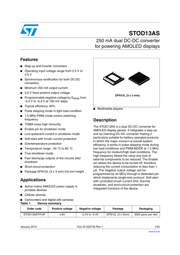
📄 Preview 📖 Table of Contents Contents PAGE OF 25

Page 1 Text Content

STOD13AS

250 m A dual DC-DC converter for powering AMOLED displays

Features Step-up and inverter converters Operating input voltage range from 2.5 V to 4.5 Synchronous rectification for both DC-DC converters Minimum 250 m A output current 4.6 V fixed positive output voltage

DFN12L (3 x 3 mm)

Programmable negative voltage by SWIRE from -2.4 V to -6.4 V at 100 m V steps Typical efficiency: 85%

Multimedia players

Pulse skipping mode in light load condition 1.5 MHz PWM mode control switching frequency

Description

TDMA noise high immunity

The STOD13AS is a dual DC-DC converter for

Enable pin for shutdown mode

AMOLED display panels. It integrates a step-up Low quiescent current in shutdown mode and an inverting DC-DC converter making it particularly suitable for battery operated products,

Soft-start with inrush current protection

in which the major concern is overall system

Overtemperature protection

efficiency. It works in pulse skipping mode during Temperature range: -40 °C to 85 °C low load conditions and PWM-MODE at 1.5 MHz frequency for medium/high load conditions. The

True-shutdown mode

high frequency allows the value and size of

Fast discharge outputs of the circuits after

external components to be reduced. The Enable

shutdown

pin allows the device to be turned off, therefore Short-circuit protection reducing the current consumption to less than 1 µA. The negative output voltage can be

Package DFN12L (3 x 3 mm) 0.6 mm height

programmed by an MCU through a dedicated pin which implements single-wire protocol. Soft-start

Applications

with controlled inrush current limit, thermal shutdown, and short-circuit protection are

Active matrix AMOLED power supply in

integrated functions of the device.

portable devices Cellular phones Camcorders and digital still cameras Table 1. Device summary Order code Positive voltage Negative voltage Package Packaging

STOD13ASTPUR 4.6V -2.4V to -6.4V DFN12L (3 x 3mm) 3000 parts per reel

January 2012 Doc ID 022733 Rev 1 1/25

www.st.com

Page Summary Contents For ST STOD13AS Dual DC-DC Converter 250mA for AMOLED Displays - Data Manual

Page 1 STOD13AS 250 m A dual DC-DC converter for powering AMOLED displays Features Step-up and inverter converters Operating input voltage range from 2.5 V to 4.5 Synchronous rectification for both DC-DC con...
Page 2 Contents STOD13AS Contents Schematic . . . . . . . . . . . . . . . . . . . . . . . . . . . . . . . . . . . . . . . . . . . . . . . . . 3 Pin configuration . . . . . . . . . . . . . . . . . . . . . . ....
Page 3 STOD13AS Contents 8.1.9 Short-circuit protection during soft-start (SSD) . . . . . . . . . . . . . . . . . . . 18 8.1.10 Overload protection (OLP) . . . . . . . . . . . . . . . . . . . . . . . . . . ....
Page 4 Schematic STOD13AS 1 Schematic Figure 1. Application schematic VINPCIN LX1 S-WIRE S-WIRE STOD13AS EN VREF VO2 CREF CO2LX2 PGND AGND AM10459v1 Table 2. Typical external components Comp. Manufacturer Pa...
Page 5 STOD13AS Schematic Figure 2. Block schematic VINP LX1 VINA UVLO KILLER STEP-UP CONTROL EN LOGIC CONTROL OTP FAST S-WIRE DISCHARGE SWIRE VREF VREF OSC SCP VO2 OLP INVERTING CONTROL S-WIRE control VO2LX...
Page 6 Pin configuration STOD13AS 2 Pin configuration Figure 3. Pin configuration (top view) Table 3. Pin description Pin name Pin n° Description Lx1 Boost converter switching node PGND 2 Power ground pin VM...
Page 7 STOD13AS Maximum ratings 3 Maximum ratings Table 4. Absolute maximum ratings Symbol Parameter Value Unit VINA, VINP DC supply voltage -0.3 to 6 EN, SWIRE Logic input pins -0.3 to 4.6 FD Logic input pi...
Page 8 Electrical characteristics STOD13AS 4 Electrical characteristics TJ = 25 °C, VINA = VINP = 3.7 V, IMID,O2 = 30 m A, CIN = 2 x 10 µF, CMID = 10 µF, CO2 = 2 x 10 µF, CREF = 1 µF, L1 = L2 = 4.7 µH, VEN =...
Page 9 STOD13AS Electrical characteristics Table 6. Electrical characteristics (continued) Symbol Parameter Test conditions Min. Typ. Max. Unit VINA,P=3.4V to 2.9V, ΔVMID LT Line transient -10 m V IMID=100m ...
Page 10 Electrical characteristics STOD13AS Table 6. Electrical characteristics (continued) Symbol Parameter Test conditions Min. Typ. Max. Unit N-channel static drain-source VINA=VINP=3.7V, RDSONN2 0.43 0.8 ...
Page 11 STOD13AS Typical performance characteristics Effi ci en cy P_ [W 5 Typical performance characteristics VINA = VINP = 3.7 V, VO2 = -4.9 V, TJ = 25 °C; See Table 1 for external components used in the te...
Page 12 Typical performance characteristics STOD13AS Figure 8. Fast discharge no load, Figure 9. Switching and output waveforms EN=SW=FD=Low VINA = VINP = 2.9 V, IMID,O2 = 250 m A, TJ = 85 °C Figure 10. Step-...
Page 13 STOD13AS Detailed description 6 Detailed description 6.1 SWIRE Protocol: to digitally communicate over a single cable with single-wire components Single-wire's 3 components: 1. an external MCU 2. wiri...
Page 14 Detailed description STOD13AS 6.2 Negative output voltage levels Table 7. Negative output voltage levels Pulse VO2 Pulse VO2 Pulse VO2 Pulse VO2 1. Default value. 6.3 Enable, SWIRE and FD Table 8. Ena...
Page 15 STOD13AS Application information 7 Application information 7.1 External passive components 7.1.1 Inductor selection Magnetic shielded low ESR power inductors must be chosen as the key passive componen...
Page 16 Application information STOD13AS 7.2 Recommended PCB layout The STOD13AS is a high frequency power switching device and therefore requires a proper PCB layout in order to obtain the necessary stabilit...
Page 17 STOD13AS Detailed description 8 Detailed description 8.1 General description The STOD13AS is a high efficiency dual DC-DC converter which integrates a step-up and inverting power stage suitable for su...
Page 18 Detailed description STOD13AS 8.1.5 Enable pin The device operates when the EN pin is set high. If the EN pin is set low, the device stops switching, and all the internal blocks are turned off. In thi...
Page 19 STOD13AS Detailed description normal functionality (assuming that the short condition is removed), it is necessary to restart the converter through an enable transient. 8.1.11 Short-circuit protection...
Page 20 Package mechanical data STOD13AS 9 Package mechanical data In order to meet environmental requirements, ST offers these devices in different grades of ECOPACK® packages, depending on their level of en...
Page 21 STOD13AS Package mechanical data Table 10. DFN12L (3 x 3) mechanical data mm. inch. Min. Typ. Max. Min. Typ. Typ. Figure 14. DFN12L (3 x 3) drawing Doc ID 022733 Rev 1 21/25
Page 22 Package mechanical data STOD13AS Tape & reel QFNxx/DFNxx (3x3) mechanical data mm. inch MIN. TYP MAX. MIN. TYP. MAX. Ao 3.3 0.130 Bo 3.3 0.130 Ko 1.1 0.043 Po 0.157 22/25 Doc ID 022733 Rev 1
Page 23 STOD13AS Package mechanical data Figure 15. DFN12L (3 x 3 mm) footprint recommended data Doc ID 022733 Rev 1 23/25
Page 24 Revision history STOD13AS 10 Revision history Table 11. Document revision history Date Revision Changes 27-Jan-2012 Initial release. 24/25 Doc ID 022733 Rev 1
Page 25 STOD13AS Please Read Carefully: Information in this document is provided solely in connection with ST products. STMicroelectronics NV and its subsidiaries (“ST”) reserve the right to make changes, cor...

Manual Details

Brand Dual
Pages 25
File Size 689.31 KB
Published May 20, 2026
174 views

Enter the captcha to get the download link:

captcha

Frequently Asked Questions

What is the input voltage range for the STOD13AS?

It operates on an input voltage from 2.5 V up to 4.5 V.

How can I program the negative output voltage?

The negative voltage (range -2.4 V to -6.4 V) is programmed by an MCU through a dedicated pin using a single-wire protocol.

What protective features are included in this converter?

It offers short-circuit protection, overtemperature protection, and soft-start with built-in inrush current limiting.

How does the device manage power consumption during standby mode?

It achieves low quiescent current (less than 1 µA) when using its true-shutdown mode.