ROHM RPM872-H14 User Guide
Summary
This ultra-compact module provides efficient IrDA Ver. 1.2 low-power infrared communication, integrating the LED, photodiode, and LSI into one single package. Designed for portable electronics such as cell phones, PDAs, and digital cameras, it guarantees minimal power consumption while maintaining versatility across various voltage levels. The accompanying manual covers everything needed to integrate the module, including detailed electrical specifications, pin functions, timing charts, and comprehensive application guidelines, making deployment reliable and easy.
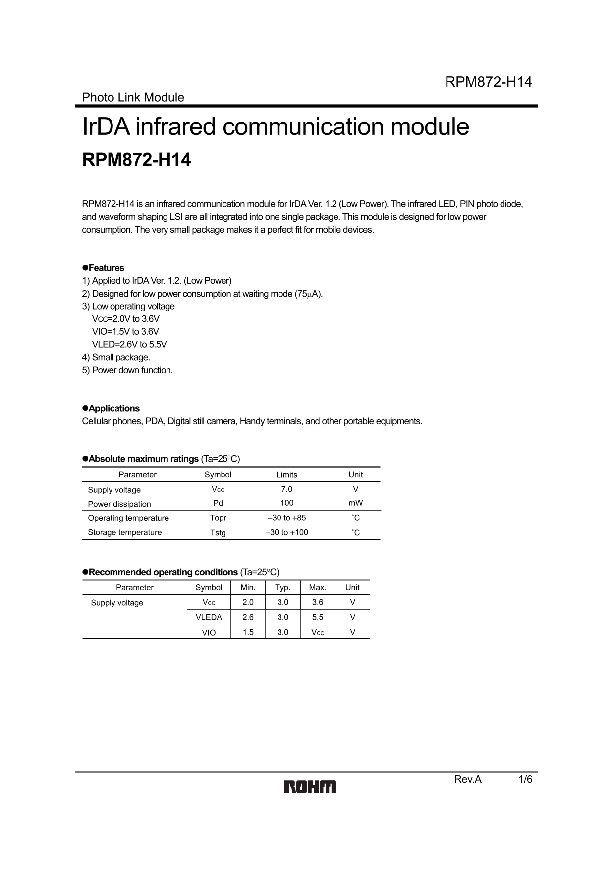
Page 1 Text Content
RPM872-H14
Photo Link Module
Ir DA infrared communication module RPM872-H14 RPM872-H14 is an infrared communication module for Ir DA Ver. 1.2 (Low Power). The infrared LED, PIN photo diode, and waveform shaping LSI are all integrated into one single package. This module is designed for low power consumption. The very small package makes it a perfect fit for mobile devices.
Features 1) Applied to Ir DA Ver. 1.2. (Low Power) 2) Designed for low power consumption at waiting mode (75µA). 3) Low operating voltage VCC=2.0V to 3.6V VIO=1.5V to 3.6V VLED=2.6V to 5.5V 4) Small package. 5) Power down function.
Applications Cellular phones, PDA, Digital still camera, Handy terminals, and other portable equipments.
Absolute maximum ratings (Ta=25°C) Parameter Symbol Limits Unit
Supply voltage VCC 7.0
Power dissipation Pd m W100
Operating temperature Topr −30 to +85 ˚C Storage temperature Tstg −30 to +100 ˚C
Recommended operating conditions (Ta=25°C) Parameter Symbol Min. Typ. Max. Unit
Supply voltage VCC 3.0 3.6 V2.0
VLEDA 3.0 5.5 V2.6
VIO 3.0 VCC V1.5
Rev.A 1/6
Page Summary Contents For ROHM RPM872-H14 User Guide
Manual Details
| Brand | ROHM |
|---|---|
| Pages | 7 |
| File Size | 88.84 KB |
| Published | July 22, 2026 |
Enter the captcha to get the download link:

Frequently Asked Questions
What are the operating voltage ranges for this module?
VCC is 2.0V to 3.6V, VIO is 1.5V to 3.6V, and VLED is 2.6V to 5.5V.
How do I put the device into a low-power state?
Connect Pin 5 (PWDOWN) to HIGH to stop the receiving circuit and LED operation.
What are the recommended peak operating characteristics?
The peak wavelength is 850 nm, and its intensity can reach up to 26 mW/Sr at a half-angle of 15°.