ROHM RPM871-H14 User Guide and Specifications
Summary
This low-power Photo Link Module provides integrated IrDA Ver. 1.2 infrared communication for mobile and battery-operated devices, such as PDAs and cellular phones. Featuring an optimized power-down function and ultra-small packaging, it ensures reliable data exchange over distances of 20–60 cm while maintaining minimal standby current consumption. The accompanying manual offers comprehensive technical details, including electrical characteristics, optical performance specifications, pin descriptions, and application circuitry necessary for seamless integration into your portable electronics design.
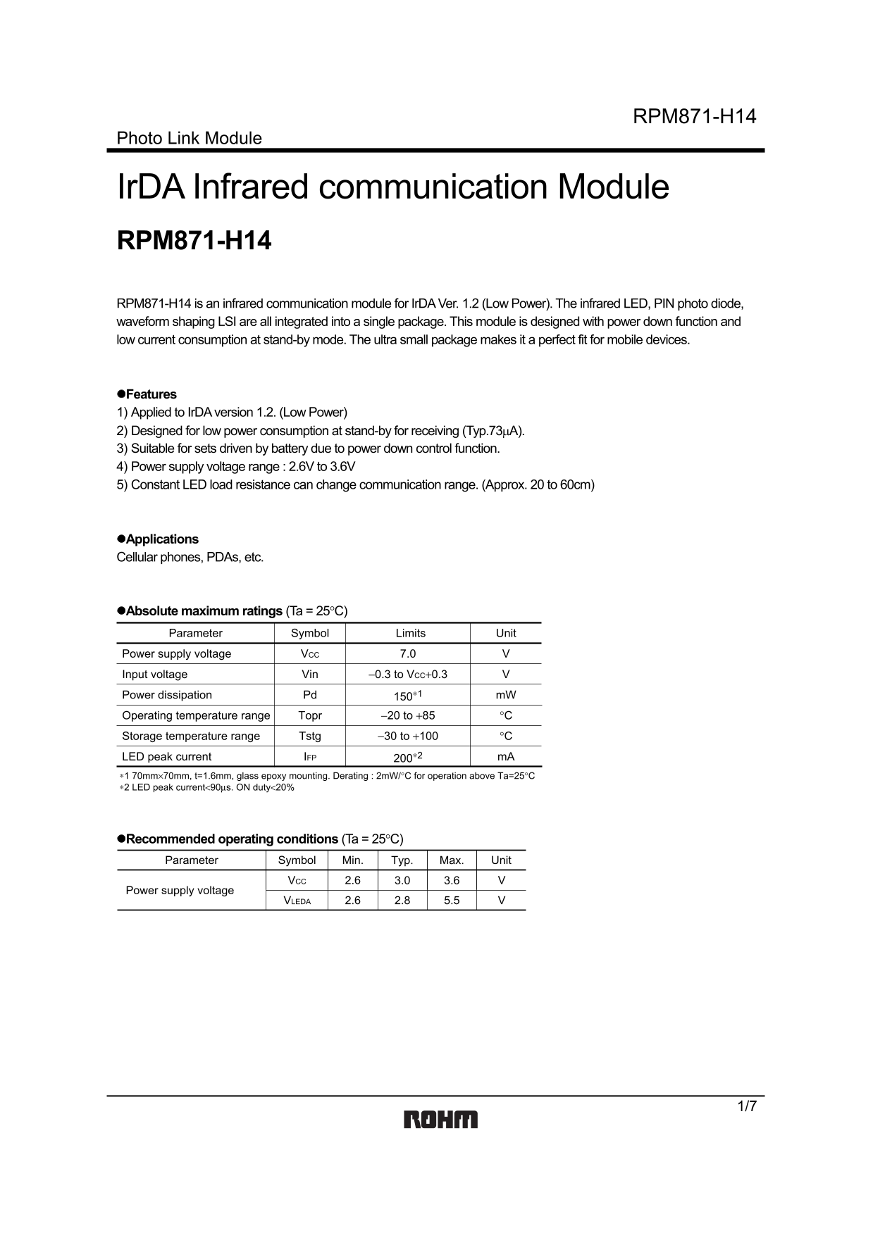
Page 1 Text Content
RPM871-H14
Photo Link Module
Ir DA Infrared communication Module RPM871-H14 RPM871-H14 is an infrared communication module for Ir DA Ver. 1.2 (Low Power). The infrared LED, PIN photo diode, waveform shaping LSI are all integrated into a single package. This module is designed with power down function and low current consumption at stand-by mode. The ultra small package makes it a perfect fit for mobile devices.
Features 1) Applied to Ir DA version 1.2. (Low Power) 2) Designed for low power consumption at stand-by for receiving (Typ.73µA). 3) Suitable for sets driven by battery due to power down control function. 4) Power supply voltage range : 2.6V to 3.6V 5) Constant LED load resistance can change communication range. (Approx. 20 to 60cm)
Applications Cellular phones, PDAs, etc.
Absolute maximum ratings (Ta = 25°C) Parameter Symbol Limits Unit Power supply voltage VCC 7.0 Input voltage Vin −0.3 to VCC+0.3 Power dissipation Pd 150∗1 m W
Operating temperature range Topr −20 to +85 °C
Storage temperature range Tstg −30 to +100 °C
LED peak current IFP 200∗2 m A
∗1 70mm×70mm, t=1.6mm, glass epoxy mounting. Derating : 2m W/°C for operation above Ta=25°C ∗2 LED peak current<90µs. ON duty<20%
Recommended operating conditions (Ta = 25°C) Parameter Symbol Min. Typ. Max. Unit
VCC 3.0 3.6 V2.6
Power supply voltage
VLEDA 2.8 5.5 V2.6
Page Summary Contents For ROHM RPM871-H14 User Guide and Specifications
Manual Details
| Brand | ROHM |
|---|---|
| Pages | 8 |
| File Size | 95.57 KB |
| Published | July 15, 2026 |
Enter the captcha to get the download link:

Frequently Asked Questions
What is required to safely connect the VCC terminals?
It is recommended to connect a capacitor between VCC (3pin) and GND (4pin) for protection against infection.
How can I control the receiving circuit remotely?
Setting Pin 5 (PWDOWN) high ('H') will stop both the receiving circuit input and the transmitting LED operation.
What are the operating voltage specifications for this module?
The power supply voltage range (VCC) is 2.6 V to 3.6 V, and the recommended VLEDA range is 2.6 V to 5.5 V.
Is this device suitable for critical life support equipment?
No, it is not intended for use in safety-critical systems like medical or aerospace machinery without consulting a sales representative first.