Philips BTA208 Series C User Guide and Manual
Summary
Explore power reliability with the BTA208 series three quadrant triacs. These components are engineered for high-power switching circuits requiring effective commutation under severe static and dynamic dV/dt and dI/dt conditions. This technical manual provides comprehensive specifications, including peak voltage ratings up to 800V, thermal characteristics, and detailed gate triggering data. It is essential documentation for electrical engineers designing robust industrial control and power conversion systems.
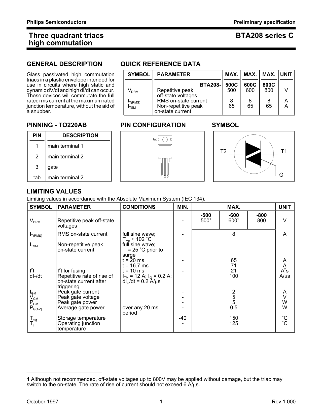
Page 1 Text Content
Philips Semiconductors Preliminary specification
Three quadrant triacs BTA208 series C high commutation
GENERAL DESCRIPTION QUICK REFERENCE DATA Glass passivated high commutation SYMBOL PARAMETER MAX. MAX. MAX. UNIT triacs in plastic envelope intended for use in circuits where high static and BTA208- 500C 600C 800C
dynamic d V/dtandhigh d I/dt can occur. VDRM Repetitive peak
These devices will commutate the full off-state voltages
ratedrms currentat the maximum rated IT(RMS) RMS on-state current
junction temperature, without the aid of ITSM Non-repetitive peak snubber. on-state current
PINNING - TO220AB PIN CONFIGURATION SYMBOL PIN DESCRIPTION
main terminal 1
main terminal 2 gate
tab main terminal 2
LIMITING VALUES Limiting values in accordance with the Absolute Maximum System (IEC 134). SYMBOL PARAMETER CONDITIONS MIN. MAX. UNIT
VDRM Repetitive peak off-state
voltages
IT(RMS) RMS on-state current full sine wave;
Tmb ≤ 102 ˚C
ITSM Non-repetitive peak full sine wave;
on-state current Tj = 25 ˚C prior to
surge t = 20 ms t = 16.7 ms
I2t I2t for fusing t = 10 ms A2s d IT/dt Repetitive rate of rise of ITM = 12 A; IG = 0.2 A; A/µs
on-state current after d IG/dt = 0.2 A/µs triggering
IGM Peak gate current VGM Peak gate voltage PGM Peak gate power PG(AV) Average gate power over any 20 ms 0.5
period
Tstg Storage temperature -40 ˚C Tj Operating junction ˚C
temperature
1 Although not recommended, off-state voltages up to 800V may be applied without damage, but the triac may switch to the on-state. The rate of rise of current should not exceed 6 A/µs.
October 1997 Rev 1.000
Page Summary Contents For Philips BTA208 Series C User Guide and Manual
Manual Details
| Brand | Philips |
|---|---|
| Pages | 5 |
| File Size | 23.45 KB |
| Published | July 07, 2026 |
Enter the captcha to get the download link:

Frequently Asked Questions
Are these triacs safe for life support applications?
No, these products are not designed for use in life support appliances or systems where malfunction could cause personal injury.
What is the safe operating junction temperature range?
The typical junction operating temperature is up to 125°C.
How high can the off-state voltage be before damage occurs?
While voltages up to 800V may be applied without damage, exceeding the limiting values can cause permanent damage and affects reliability.