Panasonic WV-Q152C Ceiling Mount Bracket Operating Instructions
Summary
Secure your network camera with this specialized ceiling mount bracket and dome enclosure. This robust system is designed to mount surveillance cameras safely onto ceilings or walls. The comprehensive manual provides technical, step-by-step installation guides, detailing best practices and crucial safety warnings regarding proper structural support and environment compatibility. It is essential reading for security professionals, installers, and technicians deploying durable, reliable commercial camera systems.
Page 1 Text Content
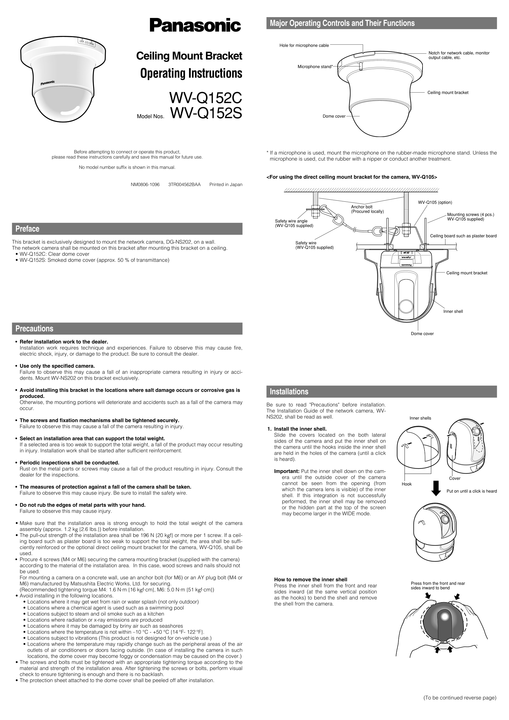
Major Operating Controls and Their Functions
Hole for microphone cable
Notch for network cable, monitor Ceiling Mount Bracket output cable, etc.
Microphone stand*
Operating Instructions
Ceiling mount bracket
WV-Q152C
Model Nos. WV-Q152S Dome cover
Before attempting to connect or operate this product, * If a microphone is used, mount the microphone on the rubber-made microphone stand. Unless the
please read these instructions carefully and save this manual for future use.
microphone is used, cut the rubber with a nipper or conduct another treatment.
No model number suffix is shown in this manual.
<For using the direct ceiling mount bracket for the camera, WV-Q105>
NM0806-1096 3TR004562BAA Printed in Japan
WV-Q105 (option)
Anchor bolt (Procured locally)
Mounting screws (4 pcs.) WV-Q105 supplied)
Safety wire angle (WV-Q105 supplied)
Preface
Ceiling board such as plaster board
This bracket is exclusively designed to mount the network camera, DG-NS202, on a wall. Safety wire
The network camera shall be mounted on this bracket after mounting this bracket on a ceiling. (WV-Q105 supplied)
WV-Q152C: Clear dome cover WV-Q152S: Smoked dome cover (approx. 50 % of transmittance)
Ceiling mount bracket
Inner shell
Precautions
Dome cover
Refer installation work to the dealer. Installation work requires technique and experiences. Failure to observe this may cause fire, electric shock, injury, or damage to the product. Be sure to consult the dealer.
Use only the specified camera. Failure to observe this may cause a fall of an inappropriate camera resulting in injury or acci- dents. Mount WV-NS202 on this bracket exclusively.
Avoid installing this bracket in the locations where salt damage occurs or corrosive gas is
Installations
produced. Otherwise, the mounting portions will deteriorate and accidents such as a fall of the camera may
Be sure to read "Precautions" before installation.
occur.
The Installation Guide of the network camera, WV- NS202, shall be read as well. Inner shells
The screws and fixation mechanisms shall be tightened securely. Failure to observe this may cause a fall of the camera resulting in injury.
1. Install the inner shell. Slide the covers located on the both lateral
Select an installation area that can support the total weight.
sides of the camera and put the inner shell on
If a selected area is too weak to support the total weight, a fall of the product may occur resulting
the camera until the hooks inside the inner shell
in injury. Installation work shall be started after sufficient reinforcement.
are held in the holes of the camera (until a click is heard).
Periodic inspections shall be conducted. Rust on the metal parts or screws may cause a fall of the product resulting in injury. Consult the
Important: Put the inner shell down on the cam-
dealer for the inspections.
era until the outside cover of the camera Cover cannot be seen from the opening (from Hook
The measures of protection against a fall of the camera shall be taken.
which the camera lens is visible) of the inner
Put on until a click is heard
Failure to observe this may cause injury. Be sure to install the safety wire.
shell. If this integration is not successfully performed, the inner shell may be removed
Do not rub the edges of metal parts with your hand.
or the hidden part at the top of the screen
Failure to observe this may cause injury.
may become larger in the WIDE mode.
Make sure that the installation area is strong enough to hold the total weight of the camera assembly (approx. 1.2 kg {2.6 lbs.}) before installation. The pull-out strength of the installation area shall be 196 N {20 kgf} or more per 1 screw. If a ceil- ing board such as plaster board is too weak to support the total weight, the area shall be suffi- ciently reinforced or the optional direct ceiling mount bracket for the camera, WV-Q105, shall be used. Procure 4 screws (M4 or M6) securing the camera mounting bracket (supplied with the camera) according to the material of the installation area. In this case, wood screws and nails should not be used. For mounting a camera on a concrete wall, use an anchor bolt (for M6) or an AY plug bolt (M4 or
How to remove the inner shell
M6) manufactured by Matsushita Electric Works, Ltd. for securing. Press from the front and rear
Press the inner shell from the front and rear
sides inward to bend
(Recommended tightening torque M4: 1.6 N·m {16 kgf·cm}, M6: 5.0 N·m {51 kgf·cm})
sides inward (at the same vertical position
Avoid installing in the following locations.
as the hooks) to bend the shell and remove
Locations where it may get wet from rain or water splash (not only outdoor)
the shell from the camera.
Locations where a chemical agent is used such as a swimming pool Locations subject to steam and oil smoke such as a kitchen Locations where radiation or x-ray emissions are produced Locations where it may be damaged by briny air such as seashores Locations where the temperature is not within –10 °C - +50 °C {14 °F- 122 °F}. Locations subject to vibrations (This product is not designed for on-vehicle use.) Locations where the temperature may rapidly change such as the peripheral areas of the air outlets of air conditioners or doors facing outside. (In case of installing the camera in such locations, the dome cover may become foggy or condensation may be caused on the cover.) The screws and bolts must be tightened with an appropriate tightening torque according to the material and strength of the installation area. After tightening the screws or bolts, perform visual check to ensure tightening is enough and there is no backlash. The protection sheet attached to the dome cover shall be peeled off after installation.
(To be continued reverse page)
Page Summary Contents For Panasonic WV-Q152C Ceiling Mount Bracket Operating Instructions
Manual Details
| Brand | Panasonic |
|---|---|
| Pages | 2 |
| File Size | 150.16 KB |
| Published | July 16, 2026 |
Enter the captcha to get the download link:

Frequently Asked Questions
What is the specialized purpose of this bracket?
It is exclusively designed to mount a network camera (WV-NS202) on a wall.
How should I properly install the inner shell?
Slide the covers and place the inner shell, ensuring hooks inside align until a click is heard. The screws must be tightened securely.
What are essential precautions for safe installation?
Ensure the installation area supports the total weight (approx. 1.2 kg). Always install the safety wire and consult a dealer.
Can I use this bracket in wet or chemical environments?
No. Avoid locations where it may get wet, or near corrosive agents like swimming pools or seashores.