Panasonic 2SJ0164 (2SJ164) User Manual and Specifications
Summary
Optimize your electronic designs with this high-performance P-Channel Junction FET, engineered for low-noise, small-signal switching applications. This technical manual provides comprehensive data, including absolute maximum ratings, detailed electrical characteristics, and performance metrics like low ON-resistance and transfer admittance. It is essential reading for electrical engineers and designers building standard electronic equipment such as communication, measuring, or general office instrumentation.
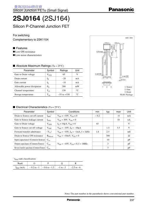
Page 1 Text Content
查询2SJ0164供应商 Silicon Junction FETs (Small Signal)
2SJ0164 (2SJ164) Silicon P-Channel Junction FET For switching
unit: mm
Complementary to 2SK1104
Features
Low ON-resistance 0.75 max.
Low-noise characteristics
Absolute Maximum Ratings (Ta = 25°C) Parameter Symbol Ratings Unit
+0.20 Gate to Drain voltage VGDS 0.45 –0.10
Drain current ID −20 m A
Gate current IG −10 m A Allowable power dissipation PD m W 1: Source
2: Gate
Channel temperature Tch °C
3: Drain
Storage temperature Tstg −55 to +150 °C NS-B1 Package
Electrical Characteristics (Ta = 25°C)
Parameter Symbol Conditions min typ max Unit (0 .8 (0 .8
Drain to Source cut-off current IDSS VDS = −10V, VGS = 0 − 0.2 −6 m A 7.
Gate to Source leakage current IGSS VGS = 30V, VDS = 0 n A Gate to Drain voltage VGDS IG = 10µA, VDS = 0 Gate to Source cut-off voltage VGSC VDS = −10V, ID = −10µA 1.5 3.5 Forward transfer admittance | Yfs | VDS = −10V, ID = −1m A, f = 1k Hz 1.8 2.5 m S Drain to Source ON-resistance RDS(on) VDS = −10m V, VGS = 0
Input capacitance (Common Source) Ciss p F Output capacitance (Common Source) Coss VDS = −10V, VGS = 0, f = 1MHz p F Reverse transfer capacitance (Common Source) Crss p F
* IDSS rank classification
Runk IDSS (m A) − 0.2 to −1 − 0.6 to −1.5 −1 to −3 −2.5 to −6
Note) The part number in the parenthesis shows conventional part number.
Page Summary Contents For Panasonic 2SJ0164 (2SJ164) User Manual and Specifications
Manual Details
| Brand | Panasonic |
|---|---|
| Pages | 3 |
| File Size | 63.96 KB |
| Published | June 17, 2026 |
Enter the captcha to get the download link:

Frequently Asked Questions
Is this component suitable for mission-critical applications like automotive or aerospace systems?
For special applications requiring exceptional quality, users must consult sales staff in advance.
What is the maximum allowable power dissipation for this device?
The datasheet specifies an allowable power dissipation (P) of 300 mW.
If my design exceeds recommended operating parameters, who assumes liability for component failure?
Users are advised that they will not be liable for any defect if the product is used outside the guaranteed values.