Panasonic 2SD0965 Data Manual
Summary
This datasheet provides comprehensive technical specifications for the 2SD0965, a Silicon NPN epitaxial planar bipolar junction transistor optimized for low-frequency power amplification. The manual details absolute maximum ratings and crucial electrical characteristics, such as low collector-emitter saturation voltage (Vce(sat)) and transition frequency (fT). It is essential documentation for electronics engineers requiring reliable and high-efficiency components in standard general electronic equipment designs.
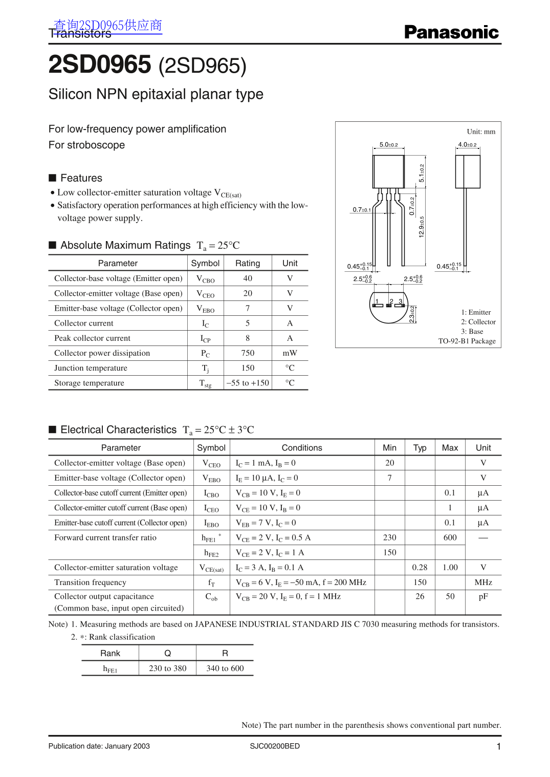
Page 1 Text Content
查询2SD0965供应商 Transistors
2SD0965 (2SD965) Silicon NPN epitaxial planar type For low-frequency power amplification Unit: mm
For stroboscope 5.0±0.2 4.0±0.2
Features Low collector-emitter saturation voltage VCE(sat) Satisfactory operation performances at high efficiency with the low-
voltage power supply.
Absolute Maximum Ratings Ta = 25°C Parameter Symbol Rating Unit
Collector-base voltage (Emitter open) VCBO 2.5+0.6 –0.2 2.5 –0.2
Collector-emitter voltage (Base open) VCEO Emitter-base voltage (Collector open) VEBO
1: Emitter Collector current IC 2: Collector 3: Base
Peak collector current ICP
TO-92-B1 Package
Collector power dissipation PC m W Junction temperature Tj °C Storage temperature Tstg −55 to +150 °C
Electrical Characteristics Ta = 25°C ± 3°C Parameter Symbol Conditions Min Typ Max Unit Collector-emitter voltage (Base open) VCEO IC = 1 m A, IB = 0 Emitter-base voltage (Collector open) VEBO IE = 10 µA, IC = 0 Collector-base cutoff current (Emitter open) ICBO VCB = 10 V, IE = 0 0.1 µA Collector-emitter cutoff current (Base open) ICEO VCE = 10 V, IB = 0 µA Emitter-base cutoff current (Collector open) IEBO VEB = 7 V, IC = 0 0.1 µA Forward current transfer ratio h FE1 * VCE = 2 V, IC = 0.5 A
h FE2 VCE = 2 V, IC = 1 A
Collector-emitter saturation voltage VCE(sat) IC = 3 A, IB = 0.1 A 0.28 1.00 Transition frequency f T VCB = 6 V, IE = −50 m A, f = 200 MHz MHz Collector output capacitance Cob VCB = 20 V, IE = 0, f = 1 MHz p F (Common base, input open circuited) Note) 1. Measuring methods are based on JAPANESE INDUSTRIAL STANDARD JIS C 7030 measuring methods for transistors. 2. Rank classification
Rank h FE1 230 to 380 340 to 600
Note) The part number in the parenthesis shows conventional part number.
SJC00200BED 1Publication date: January 2003
Page Summary Contents For Panasonic 2SD0965 Data Manual
Manual Details
| Brand | Panasonic |
|---|---|
| Pages | 3 |
| File Size | 71.63 KB |
| Published | June 22, 2026 |
Enter the captcha to get the download link:

Frequently Asked Questions
What thermal precautions must I take when designing my system with this part?
You must comply with all guaranteed values, including maximum ratings, operating power supply voltage range, and heat radiation characteristics.
What is the transistor's primary advantage for high-efficiency use?
It features a low collector-emitter saturation voltage (V_CE(sat)), ensuring satisfactory operation performance at high efficiency.
Can I use this device in specialized fields like aerospace or medical devices?
The datasheet is limited to standard applications; consult sales staff for any special applications requiring exceptional reliability.
What are the absolute maximum electrical ratings for Vce and P?
The Collector-emitter voltage (V_CEO) must not exceed 20V, and the Collector power dissipation (P_C) should stay within 750 mW.