National Semiconductor MV54ACT257-X REV 0A0 Data Sheet
Summary
This technical resource provides comprehensive data on the ACT257, a robust quad 2-input multiplexer featuring noninverting TRI-STATE outputs. It allows designers to select four bits of data from two sources and interface directly with bus systems. The manual details crucial specifications, including absolute maximum ratings, electrical characteristics (I/O current draw), timing parameters (propagation delays), and operational guidelines across a wide temperature range (-55°C to 125°C). It is essential for hardware engineers designing reliable circuitry that requires precise data path switching and bus management.
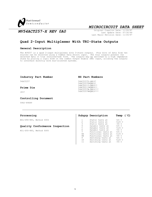
Page 1 Text Content
MICROCIRCUIT DATA SHEET Original Creation Date: 11/20/97
MV54ACT257-X REV 0A0
Last Update Date: 07/30/99
Last Major Revision Date: 11/20/97
Quad 2-Input Multiplexer With TRI-State Outputs General Description The ACT257 is a quad 2-input multiplexer with 3-state outputs. Four bits of data from two sources can be selected using a Common Data Select input. The four outputs present the selected data in true (noninverted) form. The outputs may be switched to a high impedance state by placing a logic HIGH on the common Output Enable (OE) input, allowing the outputs to interface directly with bus-oriented systems.
Industry Part Number NS Part Numbers 54ACT257 54ACT257E-QMLV*
54ACT257ERQMLV* 54ACT257J-QMLV** Prime Die 54ACT257JRQMLV** 54ACT257W-QMLV*** 54ACT257WRQMLV***
Controlling Document 5962-89689
Processing Subgrp Description Temp ( C)o MIL-STD-883, Method 5004 Static tests at +25 C
Static tests at +125 C Static tests at -55 C Quality Conformance Inspection Dynamic tests at +25 C Dynamic tests at +125 C Dynamic tests at -55 C
MIL-STD-883, Method 5005
Functional tests at +25 C
8A Functional tests at +125 C 8B Functional tests at -55 C
Switching tests at +25 C Switching tests at +125 C Switching tests at -55 C
Page Summary Contents For National Semiconductor MV54ACT257-X REV 0A0 Data Sheet
Manual Details
| Brand | National |
|---|---|
| Pages | 7 |
| File Size | 18.48 KB |
| Published | May 31, 2026 |
Enter the captcha to get the download link:

Frequently Asked Questions
How do I put the outputs into a high impedance state?
Place a logic HIGH on the common Output Enable (OE) input.
What is the required operating voltage range for reliable use?
The recommended supply voltage (Vcc) is 4.5V to 5.5V.
Does this multiplexer support bus-oriented systems?
Yes, by controlling the OE input, the outputs can interface directly with bus-oriented systems into a high impedance state.