# A B C D E F G H I J K L M N O P Q R S T U V W X Y Z

National Semiconductor LM3478 Data Sheet

Summary

The LM3478 is a high-efficiency, versatile low-side N-FET controller designed for miniature switching regulator applications. It supports various topologies—including boost and flyback converters—and operates at highly adjustable frequencies between 100kHz and 1MHz. Featuring internal soft-start, cycle-by-cycle current limiting, and robust protections (such as thermal shutdown), this controller is ideal for sophisticated power systems ranging from battery chargers and offline supplies to demanding telecom and automotive environments. The accompanying manual provides comprehensive electrical specifications, application diagrams, and integration details necessary for reliable circuit design.
📄 Preview PAGE OF 21

Page 1 Text Content

查询LM3478供应商

September

LM igh fficiency Low -S ide -C hannel C ontroller for itching egulator

LM3478 High Efficiency Low-Side N-Channel Controller for Switching Regulator

±2.5% (over temperature) internal reference

General Description

10µA shutdown current (over temperature)

The LM3478 is versatile Low-Side N-FET switching regu- lator controller. It is suitable for use in topologies requiring

Features

low side FET, such as boost, flyback, SEPIC, etc. Moreover,

the LM3478 can be operated at extremely high switching 8-lead Mini-SO8 (MSOP-8) package

frequency in order to reduce the overall solution size. The Internal push-pull driver with 1A peak current capability switching frequency of LM3478 can be adjusted to any value Current limit and thermal shutdown between 100k Hz and 1MHz by using single external resis-

Frequency compensation optimized with capacitor and

tor. Current mode control provides superior bandwidth and

resistor

transient response, besides cycle-by-cycle current limiting.

Internal softstart

Output current can be programmed with single external

Current Mode Operation

resistor.

Undervoltage Lockout with hysteresis

The LM3478 has built in features such as thermal shutdown, short-circuit protection, over voltage protection, etc. Power

Applications

saving shutdown mode reduces the total supply current to

5µA and allows power supply sequencing. Internal soft-start Distributed Power Systems

limits the inrush current at start-up. Battery Chargers

Offline Power Supplies Key Specifications Telecom Power Supplies Wide supply voltage range of 2.95V to 40V Automotive Power Systems

100k Hz to 1MHz Adjustable clock frequency

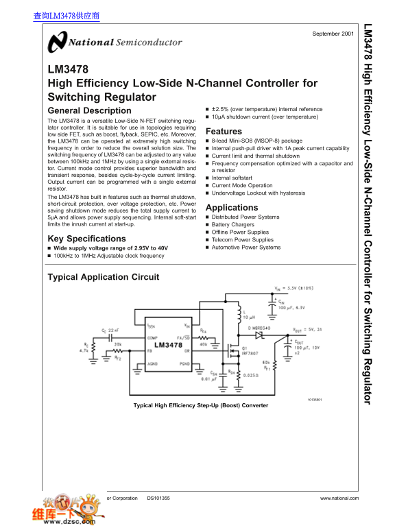
Typical Application Circuit

Typical High Efficiency Step-Up (Boost) Converter

National Semiconductor Corporation DS101355 www.national.com

Page Summary Contents For National Semiconductor LM3478 Data Sheet

Page 1 查询LM3478供应商 September LM igh fficiency Low -S ide -C hannel C ontroller for itching egulator LM3478 High Efficiency Low-Side N-Channel Controller for Switching Regulator ±2.5% (over temperature) inter...
Page 2 Connection Diagram Lead Mini SO8 Package (MSOP-8 Package) Package Marking and Ordering Information Order Number Package Type Package Marking Supplied As: LM3478MM MSOP-8 S14B units on Tape and LM3478M...
Page 3 Absolute Maximum Ratings (Note 1) DR Pin Voltage −0.4V VDR 8V If Military/Aerospace specified devices are required, ISEN Pin Voltage 500m V please contact the National Semiconductor Sales Office/ Dist...
Page 4 Electrical Characteristics (Continued) Specifications in Standard type face are for TJ 25˚C, and in bold type face apply over the full Operating Temperature Range. Unless otherwise specified, VIN 12V,...
Page 5 Electrical Characteristics (Continued) LM Note 1: Absolute Maximum Ratings are limits beyond which damage to the device may occur. Operating Ratings are conditions under which operation of the device ...
Page 6 Typical Performance Characteristics Unless otherwise specified, VIN 12V, TJ 25˚C. (Continued) Frequency vs Temperature Drive Voltage vs Input Voltage Current Sense Threshold vs Input Voltage COMP Pin ...
Page 7 Typical Performance Characteristics Unless otherwise specified, VIN 12V, TJ LM 25˚C. (Continued) Efficiency vs Load Current (9V In and 12V Out) Efficiency vs Load Current (3.3V In and 5V Out Error Amp...
Page 8 Typical Performance Characteristics Unless otherwise specified, VIN 12V, TJ 25˚C. (Continued) Compensation Ramp vs Compensation Resistor Shutdown Threshold Hysteresis vs Temperature Duty Cycle vs Curr...
Page 9 Functional Block Diagram LM The voltage sensed across the sense resistor generally Functional Description contains spurious noise spikes, as shown in Figure 1. These The LM3478 uses fixed frequency, P...
Page 10 Functional Description (Continued) FIGURE 1. Basic Operation of the PWM comparator Slope Compensation Ramp From the above equation, when 0.5, ∆I1 will be greater than ∆IO. In other words, the disturba...
Page 11 Functional Description (Continued) LM FIGURE 3. Compensation Ramp Avoids Sub-Harmonic Oscillation The compensation ramp has been added internally in LM3478. The slope of this compensation ramp has bee...
Page 12 Functional Description (Continued) FIGURE 4. Increasing the Slope of the Compensation Ramp FIGURE 5. ∆VSL vs RSL Frequency Adjust/Shutdown switching and goes into low current mode. The total supply cu...
Page 13 Functional Description (Continued) LM FIGURE 6. Frequency Adjust FIGURE 7. Shutdown Operation in Frequency Adjust Mode Short-Circuit Protection In the second cycle, MOSFET is off and the diode is forw...
Page 14 Typical Applications (Continued) FIGURE 8. Simplified Boost Converter Diagram (a) First cycle of operation. (b) Second cycle of operation Power Inductor Selection The inductor is one of the two energy...
Page 15 Typical Applications Programming the Output Voltage and Output Current (Continued) LM The output voltage can be programmed using resistor If VL(t) is constant, di L(t)/dt must be constant. Hence, for ...
Page 16 Typical Applications (Continued) FIGURE 10. Adjusting the Output Voltage Current Limit with Additional Slope Compensation The peak reverse voltage for boost converter is equal to the regulator output ...
Page 17 Typical Applications (Continued) LM where DMAX is the maximum duty cycle. The turn-on and turn-off transitions of MOSFET require times of tens of nano-seconds. CRSS and Qg are needed to FIGURE 11. Red...
Page 18 Designing SEPIC Using LM3478 In the above equation, VQ is the on-state voltage of the MOSFET, Q, and VDIODE is the forward voltage drop of the (Continued) diode. The duty cycle of SEPIC is given by: F...
Page 19 Designing SEPIC Using LM3478 the size required to meet the rms current rating can be accommodated. There is an energy balance between CS LM (Continued) and L1, which can be used to determine the value...
Page 20 Input Capacitor Selection The ESR and ESL of the output capacitor directly control the (Continued) output ripple. Use low capacitors with low ESR and ESL at The output capacitor of the SEPIC sees very...
Page 21 Physical Dimensions inches (millimeters) LM unless otherwise igh noted fficiency Low -S ide -C hannel C ontroller for itching egulator LIFE SUPPORT POLICY NATIONAL’S PRODUCTS ARE NOT AUTHORIZED FOR US...

Manual Details

Brand National
Pages 21
File Size 565.49 KB
Published June 01, 2026
77 views

Enter the captcha to get the download link:

captcha

Frequently Asked Questions

What is the operating voltage range for this controller?

The supply voltage can operate within a wide range of 2.95V to 40V.

How do I adjust the switching frequency?

A resistor connected to the FA/SD pin controls and sets the oscillator frequency between 100kHz and 1MHz.

What protection features are built into the LM3478?

It includes thermal shutdown, short-circuit protection, over voltage protection, and Undervoltage Lockout (UVLO).

How can I program the output voltage?

The output voltage must be adjusted using a resistor divider connected to the Feedback pin (FB).