NATIONAL LMV232 Data Sheet
Summary
The LMV232 is a precision dual-channel Mean Square Power Detector, specifically engineered for accurate RF transmit power measurement in advanced mobile communications systems like UMTS and WCDMA. This manual provides comprehensive details on its electrical characteristics, low-power operational modes, configurable gain settings, and application guidelines. It is the ideal component for electronics developers designing next-generation 3G devices that require reliable and highly accurate performance monitoring across diverse frequency bands.
Page 1 Text Content
February
LM ual-C hannel Integrated ean quare ow er etector for
LMV232 Dual-Channel Integrated Mean Square Power Detector for CDMA WCDMA General Description Features
The LMV232 dual RF detector is designed for RF transmit >20 d B square-law detection range power measurement in mobile phones. This dual mean sequentially selectable RF inputs
square IC is especially suited for accurate power measure- Low power consumption shutdown mode ment of RF signals exhibiting high peak-to-average ratios
Externally configurable gain and LF filter bandwidth.
used in 3G and UMTS/CDMA applications. The LMV232
Internal 50Ω RF termination impedance
saves calibration steps and system certification and is highly
Optimized for use with d B directional coupler
accurate. The circuit operates with single supply from 2.5
Lead free 8-bump micro SMD package 1.5 1.5 0.6
to 3.3V.
The LMV232 contains mean square detector with two sequentially selectable RF inputs. The RF input power range
Applications
of the device has been optimized for use with d B
directional coupler, without the need for additional external 3G mobile communications components. single external RC combination between FB UMTS
and OUT provides an externally configurable gain and LF WCDMA filter bandwidth of the device.
CDMA2000
The device has two digital interfaces. shutdown function is TD-SCDMA available to set the device in low-power shutdown mode. In
RF control
case SD HIGH, the device is in shutdown, if SD LOW the
Wireless LAN
device is active. The Band-Select function controls the se-
PC Card and GPS modules
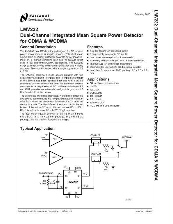
lection of the active RF input channel. In case BS HIGH, RFIN1 is active. In case BS LOW, RFIN2 is active. The dual mean square detector is offered in an 8-bump micro SMD 1.5 1.5 0.6 mm package. This micro SMD package has the smallest footprint and height.
Typical Application
National Semiconductor Corporation DS201278 www.national.com
Page Summary Contents For NATIONAL LMV232 Data Sheet
Manual Details
| Brand | National |
|---|---|
| Pages | 13 |
| File Size | 779.71 KB |
| Published | June 17, 2026 |
Enter the captcha to get the download link:

Frequently Asked Questions
What type of directional coupler is recommended for this detector?
The device is optimized for use with a 20 dB directional coupler.
How can I configure the gain and Low Filter bandwidth?
You set the gain and LF filter bandwidth using an external RC combination between FB and UMTS.
What signals control the detector’s operating mode?
The SD pin controls the shutdown function; setting SD=HIGH enters low-power shutdown mode.
What is the required supply voltage?
The device operates with a single supply voltage ranging from 2.5V to 3.3V.