# A B C D E F G H I J K L M N O P Q R S T U V W X Y Z

NATIONAL LP3931 Data Sheet

Summary

The LP3931 is a sophisticated, highly efficient RGB LED driver featuring an integrated high-current boost DC-DC converter designed for portable wireless applications. This chip provides dual sets of fully programmable RGB LEDs, allowing precise control over color, intensity, and advanced blinking patterns via the SPI interface. It enables developers to easily incorporate complex lighting features requiring stable power from single Li-Ion batteries. Ideal for electronics designers building compact devices like cellular phones or specialized displays needing customizable, energy-efficient LED solutions.
📄 Preview PAGE OF 18

Page 1 Text Content

查询LP3931供应商

August

LP ual R LE river ith igh urrent oost -D onverter

LP3931 Dual RGB LED Driver with High Current Boost DC-DC Converter General Description Features

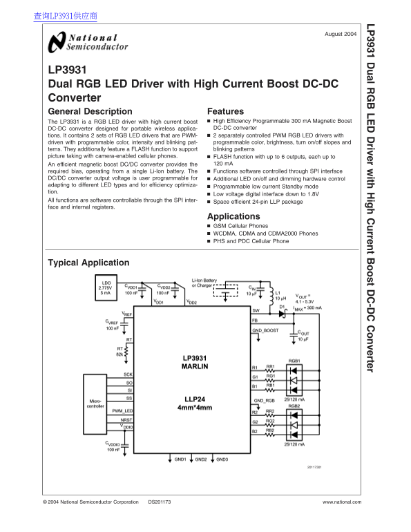
The LP3931 is RGB LED driver with high current boost High Efficiency Programmable m A Magnetic Boost DC-DC converter designed for portable wireless applica- DC-DC converter tions. It contains sets of RGB LED drivers that are PWM- separately controlled PWM RGB LED drivers with driven with programmable color, intensity and blinking pat- programmable color, brightness, turn on/off slopes and terns. They additionally feature FLASH function to support blinking patterns

picture taking with camera-enabled cellular phones. FLASH function with up to outputs, each up to

An efficient magnetic boost DC/DC converter provides the m A required bias, operating from single Li-Ion battery. The Functions software controlled through SPI interface

DC/DC converter output voltage is user programmable for Additional LED on/off and dimming hardware control adapting to different LED types and for efficiency optimiza-

Programmable low current Standby mode

tion.

Low voltage digital interface down to 1.8V

All functions are software controllable through the SPI inter-

Space efficient 24-pin LLP package

face and internal registers.

Applications GSM Cellular Phones WCDMA, CDMA and CDMA2000 Phones PHS and PDC Cellular Phone

Typical Application

National Semiconductor Corporation DS201173 www.national.com

Page Summary Contents For NATIONAL LP3931 Data Sheet

Page 1 查询LP3931供应商 August LP ual R LE river ith igh urrent oost -D onverter LP3931 Dual RGB LED Driver with High Current Boost DC-DC Converter General Description Features The LP3931 is RGB LED driver with h...
Page 2 Connection Diagrams and Package Mark Information 24-Lead LLP Package, 0.8 mm LP NS Package Number NSQAL024 View View Package Mark View Note: The actual physical placement of the package marking will v...
Page 3 Pin Description LP Pin Name Type Description G2 Output Open Drain, Green LED2 R2 Output Open Drain, Red LED2 GND_RGB Ground RGB Driver Ground R1 Output Open Drain, Red LED1 G1 Output Open Drain, Green...
Page 4 Absolute Maximum Ratings (Notes 1, ESD Rating (Note 8) 2) Human Body Model: k V LP Machine Model: 200V If Military/Aerospace specified devices are required, please contact the National Semiconductor S...
Page 5 Electrical Characteristics (Notes 2, 11) (Continued) LP Note 9: In applications where high power dissipation and/or poor package thermal resistance is present, the maximum ambient temperature may have...
Page 6 Modes of Operation RESET: In the RESET mode all the internal registers are reset to the default values (Boost output register 3Fh LP (5.0V), all other registers 00h). Reset is entered always if input ...
Page 7 Logic Interface Characteristics LP (1.8V VDD_IO VDD1,2) Symbol Parameter Conditions Min Typ Max Units LOGIC INPUTS SS, SI, SCK, PWM_LED VIL Input Low Level 0.5 VIH Input High Level VDD_IO 0.5 II Logic...
Page 8 SPI Interface (Continued) SPI Timing Diagram SPI Timing Parameters VDD1,2 VDD_IO 2.775V Limit Symbol Parameter Units Min Max Cycle Time ns Enable Lead Time ns Enable Lag Time ns Clock High Time ns Clo...
Page 9 Magnetic Boost DC/DC Converter (Continued) LP Boost Converter Topology Magnetic Boost DC/DC Converter Electrical Characteristics Symbol Parameter Conditions Min Typ Max Units 3.0V VIN 4.5V ILOAD Load ...
Page 10 Boost Output Voltage Control Boost Output Voltage Control User can control the boost output voltage by 8-bit boost LP output register as follows: Register 0DH BOOST Output Voltage Boost Output [7:0] (...
Page 11 Boost Converter Typical Performance Characteristics VIN 3.6V, VOUT 5.0V if not LP otherwise stated. (Continued) Boost Typical Waveforms at m A Load Boost Startup with No Load Boost Line Regulation Boo...
Page 12 In the FLASH mode all the outputs are controlled in one Multiple RGB LED Drivers phase and the PWM period is µs. The time averaged The RGB driver has six outputs that can independently drive LP FLASH ...
Page 13 RGB Driver Electrical Characteristics LP (R1, G1, B1, R2, G2, B2 outputs) Symbol Parameter Conditions Min Typ Max Units RDS-ON ON Resistance 3.5 ILEAKAGE Off State Leakage Current VFB 5V, LED driver o...
Page 14 RGB LED PWM Control (Note 14) (Continued) RSW1 Enable for R1 switch LP GSW1 Enable for G1 switch BSW1 Enable for B1 switch RSW2 Enable for R2 switch GSW2 Enable for G2 switch BSW2 Enable for B2 switch...
Page 15 Recommended External Components (Continued) LP List of External Components Symbol Symbol Explanation Value Unit Recommended Type CVDD1 VDD1 Bypass Capacitor n F Ceramic, X7R CVDD2 VDD2 Bypass Capacito...
Page 16 Application Examples LP3931 with One RGB and One FLASH LED LP3931 with Two RGB and One FLASH LED www.national.com
Page 17 Physical Dimensions inches (millimeters) unless otherwise noted LP ual R LE river ith igh urrent oost -D onverter 24-Lead LLP Package, 0.8 mm NS Package Number NSQAL024 LIFE SUPPORT POLICY NATIONAL’S ...
Page 18 WWW.ALLDATASHEET.COM Copyright © Each Manufacturing Company. All Datasheets cannot be modified without permission. This datasheet has been download from : www.All Data Sheet.com 100% Free Data Sheet S...

Manual Details

Brand National
Pages 18
File Size 374.92 KB
Published May 31, 2026
75 views

Enter the captcha to get the download link:

captcha

Frequently Asked Questions

How is the LP3931 device primarily controlled?

All functions are software controllable through the SPI interface and internal registers.

Can I customize the LED behavior beyond basic on/off?

Yes, it supports programmable color, intensity, blinking patterns, and smooth turn-on/off slopes. It also has a dedicated FLASH function.

What type of power source is required for operation?

It operates from a single Li-Ion battery and utilizes an efficient magnetic boost DC/DC converter.

Can the output voltage be adjusted by the user?

Yes, the DC/DC converter output voltage is user programmable for optimal bias.