# A B C D E F G H I J K L M N O P Q R S T U V W X Y Z

National LMC6022 Data Sheet/Manual

Summary

Comprehensive datasheet for National Semiconductor LMC6022 CMOS dual operational amplifier fabricated with advanced Double-Poly Silicon-Gate CMOS process. This ultra-low power device achieves 40fA input bias current with operating range from single +5V to +15V or dual supplies. Features include input common-mode range extending to negative rail, 120dB voltage gain, 0.11V/μs slew rate, and 0.5mW power consumption. Target applications include high-impedance buffers, current-to-voltage converters,
📄 Preview PAGE OF 16

Page 1 Text Content

查询LMC6022供应商

LM Low ow er ual O perational A plifier

November

LMC6022 Low Power CMOS Dual Operational Amplifier

Ultra low input bias current: f A

General Description

Input common-mode range includes V−

The LMC6022 is CMOS dual operational amplifier which

Operating range from +5V to +15V supply

can operate from either single supply or dual supplies. Its

Low distortion: 0.01% at k Hz

performance features include an input common-mode range

that reaches V−, low input bias current, and voltage gain (into Slew rate: 0.11 V/µs 100k and kΩ loads) that is equal to or better than widely Micropower operation: 0.5 m W

accepted bipolar equivalents, while the power supply re- quirement is less than 0.5 m W. Applications This chip is built with National’s advanced Double-Poly High-impedance buffer or preamplifier Silicon-Gate CMOS process.

Current-to-voltage converter

See the LMC6024 datasheet for CMOS quad operational Long-term integrator amplifier with these same features.

Sample-and-hold circuit Peak detector

Features Medical instrumentation Specified for kΩ and kΩ loads Industrial controls High voltage gain: d B Low offset voltage drift: 2.5 µV/˚C

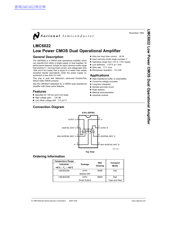
Connection Diagram

8-Pin DIP/SO

DS011236-1

Ordering Information

Temperature Range

NSC Transport

Industrial Package

Drawing Media

−40˚C TJ +85˚C

LMC6022IN 8-Pin N08E Rail

Molded DIP

LMC6022IM 8-Pin M08A Rail

Small Outline Tape and Reel

National Semiconductor Corporation DS011236 www.national.com

Page Summary Contents For National LMC6022 Data Sheet/Manual

Page 1 查询LMC6022供应商 LM Low ow er ual O perational A plifier November LMC6022 Low Power CMOS Dual Operational Amplifier Ultra low input bias current: f A General Description Input common-mode range includes V...
Page 2 Absolute Maximum Ratings (Note 1) Current at Input Pin ±5 m A Output Short Circuit to V− (Note 2) Differential Input Voltage ±Supply Voltage Output Short Circuit to V+ (Note 12) Supply Voltage (V+ V−)...
Page 3 DC Electrical Characteristics (Continued) The following specifications apply for V+ 5V, V− 0V, VCM 1.5V, VO 2.5V, and RL 1M unless otherwise noted. Bold- face limits apply at the temperature extremes;...
Page 4 AC Electrical Characteristics The following specifications apply for V+ 5V, V− 0V, VCM 1.5V, VO 2.5V, and RL 1M unless other otherwise noted. Boldface limits apply at the temperature extremes; all oth...
Page 5 Typical Performance Characteristics VS ±7.5V, TA 25˚C unless otherwise specified Supply Current Input Bias Current Input Common-Mode vs Supply Voltage vs Temperature Voltage Range vs Temperature DS011...
Page 6 Typical Performance Characteristics VS ±7.5V, TA 25˚C unless otherwise specified (Continued) Power Supply Rejection Open-Loop Voltage Gain Open-Loop Ratio vs Frequency vs Temperature Frequency Respons...
Page 7 Typical Performance Characteristics VS ±7.5V, TA 25˚C unless otherwise specified (Continued) Non-Inverting Small Inverting Large-Signal Inverting Small-Signal Signal Pulse Response Pulse Response Puls...
Page 8 Application Hints termined based on the current sinking capability of the ampli- (Continued) fier with respect to the desired output swing. Open loop gain ing load resistance of kΩ or less, the gain w...
Page 9 Application Hints (Continued) DS011236-8 FIGURE 4. Example of Guard Ring in P.C. Board Layout (Using the LMC6024) DS011236-10 (b) Non-Inverting Amplifier DS011236-9 (a) Inverting Amplifier DS011236-11...
Page 10 Application Hints (Continued) DS011236-13 (Input pins are lifted out of PC board and soldered directly to components. All other pins connected to PC board.) DS011236-14 FIGURE 6. Air Wiring FIGURE 7. ...
Page 11 Typical Single-Supply Applications (V+ 5.0 VDC) (Continued) Low-Leakage Sample-and-Hold DS011236-17 Instrumentation Amplifier DS011236-18 If R1 R5, R3 R6, and R4 R7; Then ∴AV for circuit shown For goo...
Page 12 Typical Single-Supply Applications Power Amplifier (V+ 5.0 VDC) (Continued) Sine-Wave Oscillator DS011236-21 DS011236-19 Oscillator frequency is determined by R1, R2, C1, and C2: f OSC 1/2πRC where R1...
Page 13 Typical Single-Supply Applications (V+ 5.0 VDC) (Continued) Hz Bandpass Filter Hz High-Pass Filter (2 d B Dip) DS011236-23 fc Hz DS011236-22 0.895 f O Hz Gain 2.1 Gain −8.8 Hz Low-Pass Filter (Maximal...
Page 15 Physical Dimensions inches (millimeters) unless otherwise noted 8-Pin Small Outline Molded Package (M) Order Number LMC6022IM NS Package Number M08A 8-Pin Molded Dual-In-Line Package (N) Order Number ...
Page 16 LM Lo ow er ua l O pe ra tio na l A pl ifi er LIFE SUPPORT POLICY NATIONAL’S PRODUCTS ARE NOT AUTHORIZED FOR USE AS CRITICAL COMPONENTS IN LIFE SUPPORT DE- VICES OR SYSTEMS WITHOUT THE EXPRESS WRITTEN...

Manual Details

Brand National
Pages 16
File Size 342.47 KB
Published June 16, 2026
11 views

Enter the captcha to get the download link:

captcha

Frequently Asked Questions

What is the operating voltage range for this dual amplifier?

It can operate from single or dual supplies with a functional supply voltage range of 4.75V to 15.5V.

What are its primary low-power features?

It offers micropower operation and an ultra-low input bias current, while maintaining wide performance specs.

What is the recommended industrial temperature range?

The device operates within a specified temperature range of -40°C to +85°C.

How good is its common-mode rejection ratio (CMRR)?

The typical CMRR provided under standard conditions is 83 dB, with up to 63 dB at temperature extremes.