Linear Design Features LTMag-V18N02-12- LT3592 - Bill Martin Owner's Manual
Summary
The LT3592 is a specialized LED driver designed for reliable and accurate dual-level brightness control in demanding automotive and industrial applications. This manual details how the chip eliminates the need for complex PWM signals, providing simple yet consistent bright and dim output levels seamlessly switching between them. Ideal for engineers developing brake lights, warning systems, or other high-voltage signaling LEDs, the LT3592 features rugged performance up to 36V input while ensuring stable current delivery across diverse working environments.
Page 1 Text Content
L DESIGN IDEAS
No PWM Signal Needed for Accurate Dim/Bright Control of Automotive Brake Lights and Other Signal LEDs Introduction by Bill Martin
LEDs are quickly becoming standard VIN
VIN BOOST
7V TO 32V
lighting for a variety of commercial, 1µF LT3592 0.1µF
automotive, and industrial applica- SW
tions. Some of these applications CMMSHI-40
require wide-range brightness control,
EF FI CI EN CY
spurring a demand for products that SHDN
ON 200/20m V 0.4Ω
offer PWM-based LED brightness BRIGHT OUT
BRAKE
control. However, many applications 51k
RT LUXEON
only require two settings, bright and VFB LXK2-PD12-S00 GND
dim, so generating a PWM signal for a 10k
900k Hz
binary choice is inconvenient overkill. The LT3592 LED driver is the solution to this problem. It simplifies design Figure 1. Two red LED application with no external boost diode by offering two LED current settings
with a 10:1 ratio, selected via a simple digital control pin. This pin has a low
VIN BOOST
threshold voltage, but high voltage 5V TO 16V
1µF LT3592 0.1µF 15µH
capability, making it very easy to
plug into any automotive or industrial
MBRA120
system. For an application such as
DA automotive brake light control, the CAP
ONOFF SHDN
LT3592’s accurate, consistent output 0.4Ω 22µF
FAULT BRIGHT OUT
current levels and easy to use small
package make it a perfect fit. Further- RT
LUXEON
more, the LT3592 is rugged enough LXK2-PD12-S00GND
400k Hz
to tolerate a 36V maximum input, making it useful in a wide variety of higher voltage applications. Figure 2. Single red LED application with external boost diode to VIN
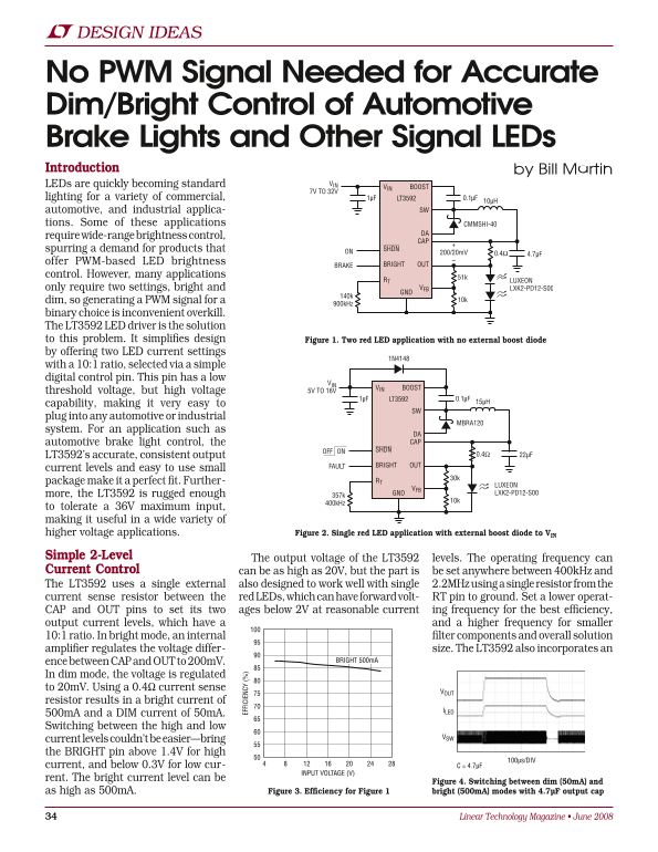
Simple 2-Level The output voltage of the LT3592 levels. The operating frequency can Current Control can be as high as 20V, but the part is be set anywhere between 400k Hz and The LT3592 uses a single external also designed to work well with single 2.2MHz using a single resistor from the current sense resistor between the red LEDs, which can have forward volt- RT pin to ground. Set a lower operat- CAP and OUT pins to set its two ages below 2V at reasonable current ing frequency for the best efficiency, output current levels, which have a and a higher frequency for smaller 10:1 ratio. In bright mode, an internal filter components and overall solution amplifier regulates the voltage differ- size. The LT3592 also incorporates an
ence between CAP and OUT to 200m V. BRIGHT 500m A
In dim mode, the voltage is regulated to 20m V. Using a 0.4Ω current sense
resistor results in a bright current of
500m A and a DIM current of 50m A. Switching between the high and low
current levels couldn’t be easier—bring the BRIGHT pin above 1.4V for high
100µs/DIV
current, and below 0.3V for low cur- C = 4.7µF
INPUT VOLTAGE (V)
rent. The bright current level can be
Figure 4. Switching between dim (50m A) and
as high as 500m A. Figure 3. Efficiency for Figure 1 bright (500m A) modes with 4.7µF output cap
Linear Technology Magazine • June 2008
Page Summary Contents For Linear Design Features LTMag-V18N02-12- LT3592 - Bill Martin Owner's Manual
Manual Details
| Brand | Linear |
|---|---|
| Pages | 2 |
| File Size | 279.00 KB |
| Published | June 19, 2026 |
Enter the captcha to get the download link:

Frequently Asked Questions
What is the LT3592's primary purpose?
It is an LED driver solution that simplifies design by offering two adjustable current settings (bright and dim) via a digital control pin.
How can I adjust the brightness levels?
Switching between modes is done by applying the BRIGHT pin above 1.4V for high current, or below 0.3V for low current.
What are the operational limitations of this device?
It can tolerate a maximum input voltage of 36V and operates with an output frequency set between 400kHz and 2.2MHz.
Does the LT3592 offer protection features?
Yes, it includes an internal Schottky diode to save components, and has a catch diode current sense limit function that protects against high input voltages.