LINEAR DESIGN FEATURES LTMag-V17N01-04-LTC2854_55 Tanghe Technical Manual
Summary
The LTC2854 and LTC2855 are advanced transceivers designed for reliable, high-speed RS485/RS422 communication. This manual details how these chips maintain signal integrity by featuring integrated, switchable termination resistors and robust ESD protection. Ideal for engineers building extended industrial or system management networks, the devices prevent data corruption from reflections and allow networks to expand seamlessly without complex physical interventions, ensuring maximum uptime even in harsh environments.
Page 1 Text Content
L DESIGN FEATURES
Rugged 3.3V RS485/RS422 Transceivers with Integrated Switchable Termination
by Steven Tanghe and Ray Schuler
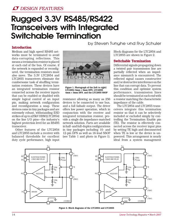
Introduction Medium and high speed RS485 net- Block diagrams for the LTC2854 and works must be terminated to avoid LTC2855 are shown in Figure 2. data-corrupting reflections. This
means a termination resistor is placed Switchable Termination
at each end of the bus. Of course, if Differential signals propagating down the network is expanded or reconfig- a twisted pair transmission line are ured, the termination resistors must partially reflected when an imped- also move. The 3.3V LTC2854 and ance mismatch is encountered. The LTC2855 transceivers eliminate the reflected signal causes constructive cumbersome task of shuffling termi- and/or destructive interference on the nation resistors. These devices have line that can corrupt data. To prevent
Figure 1. Photograph of the (left to right)
an integrated termination resistor this condition and optimize system
LTC2854 3mm × 3mm DFN, LTC2855
connected across the receiver inputs 4mm × 3mm DFN, and the LTC2855 SSOP performance, transmission lines that can be enabled or disabled with should be terminated at each end with simple logical control of an input resistance allowing as many as 256 a resistor matching the characteristic pin, making network configuration devices to be connected to one bus, impedance of the cable. and reconfiguration a snap. These and a full failsafe output. The driver The LTC2854 and LTC2855 trans- devices come in tiny packages and are offers low power operation, which in ceivers integrate this termination extremely robust, withstanding ESD conjunction with the receiver and resistor so that it can be selectively strikes of up to ±25k V HBM (LTC2854) integrated termination resistor, pro- included or excluded simply by con- on the line I/O pins—the industry’s vide a single die impedance-matched trolling the Termination Enable pin highest protection level for an RS485 network solution. Parts are available (TE). The resistor is effectively con- transceiver. in half- and full-duplex configurations nected across the receiver input pins Other features of the LTC2854 in tiny packages including 10- and by setting TE high and disconnected and LTC2855 include a receiver with 12-pin DFN as well as 16-lead SSOP when TE is low or the device is un- balanced thresholds for excellent (see Table 1 and photo in Figure 1). powered. This arrangement is nearly duty cycle performance, high input ideal from a system management
VCC VCC
RE RE
SLEEP/SHUTDOWN SLEEP/SHUTDOWN
LOGIC AND DELAY LOGIC AND DELAY
RTERM DE RTERMDE
125k TE 125k TE
RIN RIN
RO RECEIVER RO RECEIVER
125k 125k RIN RIN
DI DRIVER DI DRIVER
GND GNDLTC2854 LTC2855
Figure 2. Block diagrams of the LTC2854 and LTC2855
Linear Technology Magazine • March 2007
Page Summary Contents For LINEAR DESIGN FEATURES LTMag-V17N01-04-LTC2854_55 Tanghe Technical Manual
Manual Details
| Brand | Linear |
|---|---|
| Pages | 4 |
| File Size | 755.24 KB |
| Published | June 02, 2026 |
Enter the captcha to get the download link:

Frequently Asked Questions
How do I prevent data corruption when expanding an RS485 network?
Use transceivers with integrated switchable termination resistors (LTC2854/LTC2855) to maintain impedance matching and minimize reflections.
Do the integrated transceivers offer protection against electrical surges?
Yes, they provide ESD protection up to ±25kV HBM strikes on the line I/O pins, offering high levels of system protection.
How is the termination resistance controlled on these devices?
The termination resistor can be selectively enabled or disabled using simple logical control of a Terminal Enable (TE) pin.