# A B C D E F G H I J K L M N O P Q R S T U V W X Y Z

Idec OPENNET CONTROLLER User Manual

Summary

The OPENNET CONTROLLER PID Instruction offers sophisticated, built-in Proportional, Integral, and Derivative (PID) control algorithms for advanced automation systems. This module calculates precise manipulated outputs by reading process variables (like temperature) via analog I/O modules. The comprehensive manual guides users through system setup, including auto-tuning features to optimize critical parameters such as proportional gain and integral time. Ideal for engineers needing robust feedback loop control in industries like HVAC or process manufacturing.
📄 Preview 📖 Table of Contents Contents PAGE OF 18

Page 1 Text Content

April 22, 2002

OPENNET CONTROLLER

PID INSTRUCTION

Page Summary Contents For Idec OPENNET CONTROLLER User Manual

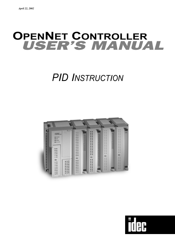
Page 1 April 22, 2002 OPENNET CONTROLLER PID INSTRUCTION
Page 2 PID INSTRUCTION Introduction The PID instruction implements a PID (proportional, integral, and derivative) algorithm with built-in auto tuning to deter- mine PID parameters, such as proportional gain,...
Page 3 PID INSTRUCTION Source Operand S1 (Control Register) Store appropriate values to data registers starting with the operand designated by S1 before executing the PID instruction as required, and make su...
Page 4 PID INSTRUCTION S1+0 Process Variable (after conversion) When the linear conversion is enabled (S1+4 set to 1), the data register designated by operand S1+0 stores the linear con- version result of th...
Page 5 PID INSTRUCTION S1+3 Operation Mode When the start input for the PID instruction is turned on, the CPU module checks the value stored in the data register des- ignated by S1+3 and executes the selecte...
Page 6 PID INSTRUCTION Example: When the transducer connected to the analog input module has an input range of –50°C through +199°C, set the following values. The temperature values are multiplied by 10 to c...
Page 7 PID INSTRUCTION When the derivative time is set to a large value, the derivative action becomes large. When the derivative action is too large, hunching of a short period is caused. While the PID acti...
Page 8 PID INSTRUCTION Example – Sampling period: 80 msec, Scan time: 60 msec (Sampling period > Scan time) 1 scan 1 scan 1 scan 1 scan 1 scan 1 scan 1 scan 1 scan 60 msec 60 msec 60 msec 60 msec 60 msec ...
Page 9 PID INSTRUCTION S1+16 Output Manipulated Variable Upper Limit The value contained in the data register designated by operand S1+16 specifies the upper limit of the output manipulated variable (S1+1) i...
Page 10 PID INSTRUCTION Set the AT sampling period to a long value to make sure that the current process variable is smaller than or equal to the pre- vious process variable during direct control action (S2+0...
Page 11 PID INSTRUCTION Source Operand S2 (Control Relay) Turn on or off appropriate outputs or internal relays starting with the operand designated by S2 before executing the PID instruction as required. Ope...
Page 12 PID INSTRUCTION S2+2 Output Manipulated Variable Limit Enable The output manipulated variable upper limit (S1+16) and the output manipulated variable lower limit (S1+17) are enabled or disabled using ...
Page 13 PID INSTRUCTION Source Operand S3 (Set Point) The PID action is executed to adjust the process variable (S1+0) to the set point (S3). When the linear conversion is disabled (S1+4 set to 0), set a requ...
Page 14 PID INSTRUCTION Destination Operand D1 (Manipulated Variable) The data register designated by destination operand D1 stores the manipulated variable of –32768 through 32767 calcu- lated by the PID act...
Page 15 PID INSTRUCTION Application Example This application example demonstrates a PID control for a heater to keep the temperature at 200°C. In this example, when the program is started, the PID instruction...
Page 16 PID INSTRUCTION System Setup Relay Output Module Analog Input Module CPU Module FC3A-R161 FC3A-AD1261 Ry A/D OUT POWER RUN ERROR HSC OUT Transducer –50° to 500°C Thermocouple _24V DC High Alarm Light ...
Page 17 PID INSTRUCTION Ladder Program The ladder diagram shown below describes an example of using the PID instruction. The user program must be modified according to the application and simulation must be p...
Page 18 PID INSTRUCTION Ladder Program (continued) While monitor input I1 is on, the temperature is monitored. CMP>=(W) S2 – D1 – REPS1 – When the temperature is higher than or equal to 250°C, M10 is turne...

Manual Details

Brand IDEC
Pages 18
File Size 890.87 KB
Published May 23, 2026
120 views

Enter the captcha to get the download link:

captcha

Frequently Asked Questions

What is the primary function of the PID instruction?

It implements a PID algorithm to determine parameters and perform automatic control, primarily for analog input/output applications like temperature control.

Which inputs are required when using the PID instruction?

You need source operands for Source 1 (Control register), Source 2 (Control relay), Source 3 (Set point), and Source 4 (Process variable).

How must emergency circuits be configured when performing feedback control?

Emergency stop and interlocking circuits must be configured outside the OpenNet Controller to prevent equipment damage or accidents.

After setting up PID control, what is recommended before actual application?

Perform simulation tests by changing the set point (S3) and process variable (S4) to anticipated values to account for disturbances.

Can I use auto-tuning to set my PID parameters?

The instruction has built-in auto-tuning capability, but because optimal performance depends on the specific application, you must manually adjust the parameters afterwards.