Page 1
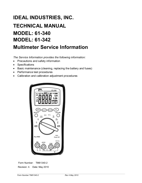
IDEAL INDUSTRIES, INC. TECHNICAL MANUAL MODEL: 61-340 MODEL: 61-342 Multimeter Service Information The Service Information provides the following information: Precautions and safety information Specif...
Page 2
TABLE OF CONTENTS Page Introduction 1 Precautions and Safety Information 1 Symbols 1 Safety 2 Specifications 3 General Specifications 3 Measurement Characteristics 4 Voltage Specifications 4 Current S...
Page 3
Introduction Warning To avoid shock or injury, do not perform the verification tests or calibration procedures described in the manual unless you are qualified to do so. The information provided in th...
Page 4
SAFETY Review the following safety precautions to avoid injury and prevent damage to this product or any products connected to it. To avoid potential hazards, use the product only as specified. For op...
Page 5
SPECIFICATIONS All specifications are warranted unless noted typical and apply to the 61-340 & 61-342 Stated accuracies are at 23°C±5°C at less than 75% relative humidity and without the battery i...
Page 6
Measurement Characteristics Accuracy is ±(% reading + number of digits) at 23°C ± 5°C, less than 75% R.H. (1) DC Volts (for 61-340 / 61-342) Over voltage Range Resolution Accuracy protection ±(0.5% re...
Page 7
(3b) DC Current (61-340 / 61-342) Range Resolution Accuracy Input Protection 4.000A 0.001A 10A, 500V Fast Blow ±(1.5% reading + 5 digits) Fuse 10.00A* 0.01A Overload Protection: A Input: 10A, 500V Fas...
Page 8
(5) Resistance (for 61-340 / 61-342) Over voltage Range Resolution Accuracy protection 400.0Ω ** 0.1Ω ±(1.2% reading + 5 digits) 4.000KΩ 1Ω ±(1.0% reading + 2 digits) 40.00KΩ 10Ω 600Vrms 400.0KΩ 100Ω ...
Page 9
(8) Frequency (for 61-340 / 61-342) Overload Range Resolution Sensitivity Accuracy protection 10.00Hz 0.01Hz 100.0Hz 0.1Hz 1.000KHz 1Hz 0.7V rms Frequency: 10.00KHz 10Hz 600V rms (± 0.1% + 3 digit) 10...
Page 10
(14) REL Press this button to have the meter enter relative measuring state and the “Δ” symbol will appear on the LCD. The result of the relative measurement is the difference between the measuring va...
Page 11
Physical and Environmental Characteristics Characteristics Description 180mm(H) ×91mm (W) ×43mm(D) (with holster) Dimensions (H×W×D) Weight (with battery& holster) 0.379Kg (13.4 oz.) Environmental...
Page 12
Required Equipment Required equipment is listed in Table B. If the recommended models are not available, equipment with equivalent specifications may be used. Repairs or servicing should be performed ...
Page 13
Basic Maintenance Warning To avoid shock, remove the test leads and any input signals before opening the case or replacing the battery or fuses. Opening the Meter Case Caution To avoid unintentional s...
Page 14
Replacing Fuses Warning To avoid electrical shock, remove the test leads and any input signals before replacing the battery or fuses. To prevent damage or injury, INSTALL ONLY quick acting fuses with ...
Page 15
Performance Tests The following performance tests verify the complete operability of the meter and check the accuracy of each meter function against the meter’s specifications. For operating instructi...
Page 16
Testing the Voltage Function (for 61-340 / 61-342) To verify accuracy in the AC and DC voltage ranges, do the following: 1. Turn the rotary switch to the position. 2. Connect the calibrator to the and...
Page 17
Table 2 AC Voltage Test: Step Range Input Frequency Reading 1 400m V 300.0m V 60Hz 295.0 to305.0 2 400m V 300.0m V 400Hz 295.0 to305.0 3 4V 3.000V 60Hz 2.950 to 3.050 4 4V 3.000V 400Hz 2.950 to 3.050 ...
Page 18
Table 3b DC m A Test: Step Range Source Reading 1 40m A 30.00m A 29.80 to 30.20 2 400m A 300.0m A 298.0 to 302.0 Testing the DC ampere Function (for 61-340 and 61-342) 1. Connect the calibrator to the...
Page 19
Testing the AC milliampere function: (for 61-340and 61-342) 1. Connect the calibrator to the and COM inputs on the meter. 2. Turn the rotary switch to the position. Press the SELECT button to select t...
Page 20
Testing the Resistance Function (for 61-340 / 61-342) To verify the accuracy of the resistance function, do the following: 1. Connect the calibrator to and COM on the meter. 2. Turn the rotary switch ...
Page 21
Table 6 Capacitance Test: Step Range Source Reading 1 40n F 10.00n F 9.60 to 10.40 2 40n F 30.00n F 29.00 to 31.00 3 400n F 300.0n F 290.5 to 309.5 4 4µF 3.000µF 2.905 to 3.095 5 40.00µF 30.00µF 29.05...
Page 22
Testing the Frequency Function (for 61-340 / 61-342) To verify the accuracy of the meter’s frequency function, do the following: 1. Connect the calibrator to the and COM inputs on the meter. Note: The...
Page 23
Testing the Temperature Function (for 61-340 / 61-342) To verify the accuracy of the meter’s temperature function, do the following: 1. Connect the calibrator to the and COM inputs on the meter. 2. Se...
Page 24
Calibration Procedure Recalibrate your meter: It is recommended that the multimeter be calibrated once each year. 1. Perform calibration at an ambient temperature of 23°C±2°C and a relative humidity o...
Page 25
(C) TEMP Calibration (Adjust VR3) 1. Set the rotary switch to the ºF/ ºC position. 2. Set the output of the calibrator to 300 ºC. 3. Connect the calibrator temperature output to the and COM input term...