IDEAL 61-700 61-701 200 Amp Clamp Meter User Manual
Summary
Essential professional voltage clamp meters designed for electricians and technicians performing comprehensive electrical diagnostics. This manual provides detailed instructions covering safe AC/DC operation, Non-contact Voltage detection (NCV), continuity checks, and resistance measurements. It emphasizes critical safety protocols, range selection, troubleshooting, and proper lead care, ensuring precise performance during high-stakes testing in industrial settings.
Page 1 Text Content
700 Series 200 Amp Clamp Meters
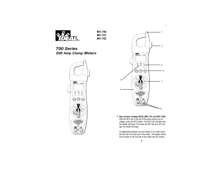
1. Non-contact voltage (NCV) (#61-701 and #61-702) With the NCV tab on the tip of the clamp close to an AC voltage, press the NCV button. The NCV LED will light and the beeper will beep. The closer the NCV tab is to AC volt- age, the louder the beep.
To differentiate between hot and neutral in an outlet, insert the NCV tab into each slot in the outlet. The beeper will be much louder on the hot side of the outlet than the neutral.
Page Summary Contents For IDEAL 61-700 61-701 200 Amp Clamp Meter User Manual
Manual Details
| Brand | Ideal |
|---|---|
| Pages | 6 |
| File Size | 143.27 KB |
| Published | May 23, 2026 |
Enter the captcha to get the download link:

Frequently Asked Questions
How do I properly maintain the test leads?
Visually inspect them for damage; if suspicious, replace them. Wrap the leads when not in use.