# A B C D E F G H I J K L M N O P Q R S T U V W X Y Z

IDEAL 61-920 Manual User Guide

Summary

This comprehensive service manual provides essential technical documentation for the Model 61-920 ground clamp/leakage current tester. It is designed exclusively for qualified technicians and maintenance professionals who require detailed knowledge for servicing and calibration. The guide covers everything from critical safety precautions and general specifications (including earth resistance testing) to in-depth performance test procedures, advanced troubleshooting guides, assembly disassembly instructions, and a full list of replacement spare parts.
📄 Preview 📖 Table of Contents Contents PAGE OF 15

Page 1 Text Content

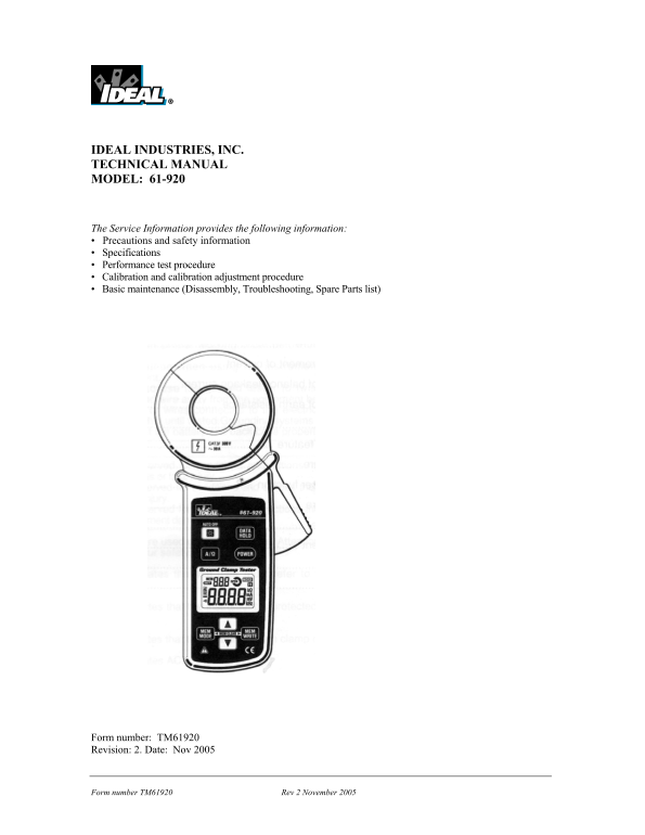
IDEAL INDUSTRIES, INC. TECHNICAL MANUAL MODEL: 61-920

The Service Information provides the following information: • Precautions and safety information • Specifications • Performance test procedure • Calibration and calibration adjustment procedure • Basic maintenance (Disassembly, Troubleshooting, Spare Parts list)

Form number: TM61920 Revision: 2. Date: Nov 2005

Form number TM61920 Rev 2 November 2005

Page Summary Contents For IDEAL 61-920 Manual User Guide

Page 1 IDEAL INDUSTRIES, INC. TECHNICAL MANUAL MODEL: 61-920 The Service Information provides the following information: • Precautions and safety information • Specifications • Performance test procedure • C...
Page 2 TABLE OF CONTENTS Title Page Introduction 1 Precautions and Symbol Information 1 Safety Information 2 Specifications 3 General Specification 3 Ground Resistance Specifications 4 Ground & Leakage C...
Page 3 Introduction Warning To avoid shock or injury, do not perform the verification tests or calibration procedures described in this manual unless you are qualified to do so. The information provided in t...
Page 4 SAFETY Review the following safety precautions to avoid injury and prevent damage to this product or any products connected to it. To avoid potential hazards, use the product only as specified. CAUTIO...
Page 5 General specifications Characteristics Description Display LCD with a maximum count of 2099 Conductor Size Approximately 1.25” in diameter max. Overrange Indication “OL” Sampling Rate Approx once per ...
Page 6 RANGES and ACCURACY SPECIFICATION Measurement Characteristics (All at 75°F ± 5°C, < 85% R.H.) Ground Resistance Range Measuring Range Resolution Accuracy 1200Ω 400Ω - 599Ω 1Ω ± 10.0% ± 10Ω 600Ω - 1...
Page 7 PERFORMANCE VERIFICATIONS Perform the following analysis, if the meter conforms to the limits listed in Table 1 the meter is functioning correctly. If the meter does not conform to any of the listed l...
Page 8 CALIBRATION (1) Calibration Preparation (1.1) This procedure consists of the following sections. (1) Calibration Preparation (2-6) Adjustments (7) Disassembly and Component Layout (8) Trouble-shooting...
Page 9 (2) Calibration Procedure It is recommended that all IDEAL meters undergo the following calibration procedure on an annual basis. POWER (2.1) Press the POWER button, without clamping anything, SW whil...
Page 10 (3.5) Repeatability check with 1000Ω and re-adjustment Press the ▲ button twice. Then “F.S” is displayed at the upper position of the LCD. Use 1000Ω resistor. Open and close the jaws, and check the re...
Page 11 (5.3) Adjust the current range (cont’d.) (d). 30.0A adjustment Press the MEM/MODE button once. Generation current: 30A@50Hz Press the MEM/WRITE button after the reading becomes stable. (saving the adj...
Page 12 (8). Trouble shooting Symptoms Possible Causes Remedies The instrument cannot be No batteries. Set the batteries. buttoned on. Faulty battery polarity Install batteries in correct polarity. Insufficie...
Page 13 (8). Trouble shooting (cont’d.) Symptoms Possible Causes Remedies When measuring Insufficient capacity of battery Replace the battery if “BATT” mark is resistance, displayed on the LCD. error of measu...
Page 14 (8). Trouble shooting (cont’d.) Incapable of saving data. Switch spacer for MEM WRITE Put the Button spacer at the specific button is missing. location. Defect of circuit component Check above points ...
Page 15 POWER SW CAL SW Fig. 3 Button layout Form number TM61920 Rev 2 November 2005

Manual Details

Brand Ideal
Pages 15
File Size 408.76 KB
Published May 23, 2026
70 views

Enter the captcha to get the download link:

captcha

Frequently Asked Questions

What operating environment is recommended for the device?

The device operates in an environment ranging from 14°F to 104°F with relative humidity up to 85%.

How does the unit conserve power when not in use?

The device has a low battery indicator and features an auto power-off function that turns it off after 10 minutes of non-use.

What caution should be followed regarding electrical testing procedures?

For safety, do not connect or disconnect probes or test leads while they are connected to a voltage source. Also, do not operate the product in wet or damp conditions.

If a continuity test on jaw wiring fails after closing the jaws, what needs replacing?

The user must replace the jaw and then perform re-adjustment.