Honeywell ML8824A Series Installation Guide
Summary
This manual provides comprehensive installation and operation instructions for the ML8824A Series Linear Electric Valve Actuator. Ideal for engineers and automation technicians, this guide details how to integrate the actuator into pneumatic or hydraulic systems. It covers advanced settings including floating control, self-adaptation modes, proportional regulation types (analog current/voltage), signal impedance matching, and various operational safeguards. Use it to achieve precise, reliable valve positioning tailored for industrial process control needs.
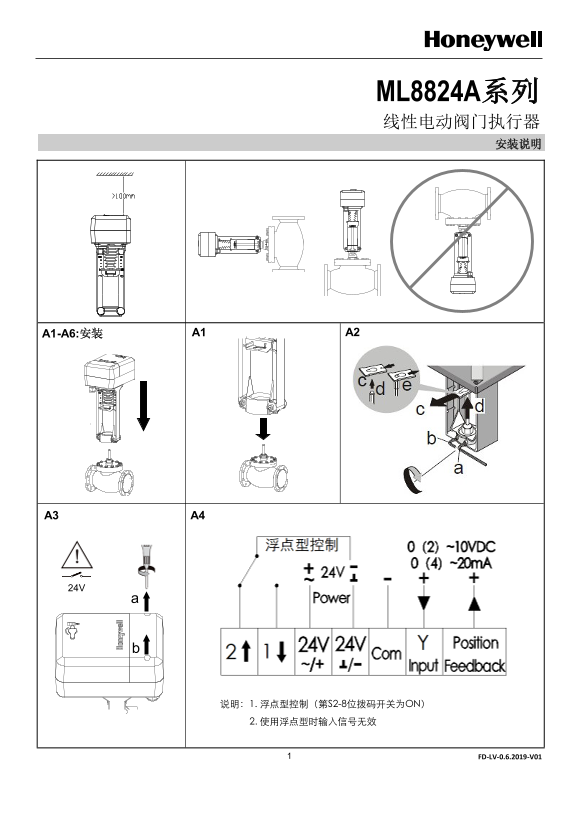
Page 1 Text Content
ML8824A系列 线性电动阀门执行器 安装说明
说明:1. 浮点型控制(第S2-8位拨码开关为ON) 2. 使用浮点型时输入信号无效
FD-LV-0.6.2019-V01
Page Summary Contents For Honeywell ML8824A Series Installation Guide
Manual Details
| Brand | Honeywell |
|---|---|
| Pages | 4 |
| File Size | 1.12 MB |
| Published | June 03, 2026 |
Enter the captcha to get the download link:

Frequently Asked Questions
How do I set the control signal to voltage or current?
Control signal type is set by S2-3. 'UI' configures it as voltage, while 'IO' configures it for current signals.
What does the self-adaptation process involve upon startup?
The actuator enters self-adaptation mode, automatically cycles from full off to full on; completion is signaled when the yellow indicator stops blinking.
What happens if the control signal line is interrupted (cut)?
If S2-6 is ON, dedicated fail-safe limits are maintained: max signal for voltage loss or min signal for current loss.
Which dip switch combination activates floating control?
Set S2-7 to ON (for general adaptation mode) and S2-8 to ON (for float control).