Fairchild Tip115 116 117 Data Handbook
Summary
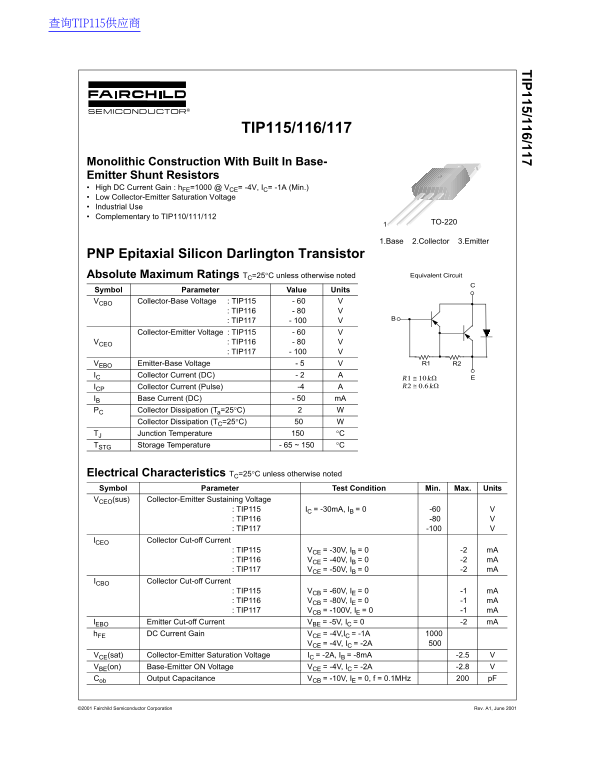
The TIP115, TIP116, and TIP117 are PNP epitaxial silicon Darlington transistors with monolithic construction and built-in base-emitter shunt resistors. Featuring high DC current gain (hFE=1000 minimum at 4V, 1A), low collector-emitter saturation voltage, and industrial-grade reliability. Available in voltage ratings of 60V (TIP115), 80V (TIP116), and 100V (TIP117) with 2A continuous collector current and 50W power dissipation. Complementary to TIP110/111/112 series. Designed for industrial control applications, power switching circuits, and equipment requiring high-gain PNP Darlington configurations.
Page 1 Text Content
查询TIP115供应商
TIP115/116/117
TIP115/116/117
Monolithic Construction With Built In Base- Emitter Shunt Resistors High DC Current Gain : h FE=1000 @ VCE= -4V, IC= -1A (Min.) Low Collector-Emitter Saturation Voltage Industrial Use Complementary to TIP110/111/112
TO-220
1.Base 2.Collector 3.Emitter
PNP Epitaxial Silicon Darlington Transistor
Absolute Maximum Ratings TC=25°C unless otherwise noted Equivalent Circuit
Symbol Parameter Value Units
VCBO Collector-Base Voltage : TIP115 - 60
: TIP116 - 80 : TIP117 - 100
Collector-Emitter Voltage : TIP115 - 60
VCEO : TIP116 - 80
: TIP117 - 100
VEBO Emitter-Base Voltage - 5 R1 R2
IC Collector Current (DC) - 2
R1 10kΩ≅ ICP Collector Current (Pulse) -4 R2 0.6kΩ≅
IB Base Current (DC) - 50 m A
PC Collector Dissipation (Ta=25°C) Collector Dissipation (TC=25°C) TJ Junction Temperature °C TSTG Storage Temperature - 65 ~ 150 °C
Electrical Characteristics TC=25°C unless otherwise noted Symbol Parameter Test Condition Min. Max. Units VCEO(sus) Collector-Emitter Sustaining Voltage
: TIP115 IC = -30m A, IB = 0 -60 : TIP116 -80 : TIP117 -100
Collector Cut-off Current
: TIP115 VCE = -30V, IB = 0 -2 m A : TIP116 VCE = -40V, IB = 0 -2 m A : TIP117 VCE = -50V, IB = 0 -2 m A
ICBO Collector Cut-off Current
: TIP115 VCB = -60V, IE = 0 -1 m A : TIP116 VCB = -80V, IE = 0 -1 m A : TIP117 VCB = -100V, IE = 0 -1 m A
VBE = -5V, IC = 0 -2 m A
IEBO Emitter Cut-off Current
DC Current Gain VCE = -4V,IC = -1A
VCE = -4V, IC = -2A
VCE(sat) Collector-Emitter Saturation Voltage IC = -2A, IB = -8m A -2.5 VBE(on) Base-Emitter ON Voltage VCE = -4V, IC = -2A -2.8 Cob Output Capacitance VCB = -10V, IE = 0, f = 0.1MHz p F
©2001 Fairchild Semiconductor Corporation Rev. A1, June 2001
Page Summary Contents For Fairchild Tip115 116 117 Data Handbook
Manual Details
| Brand | Fairchild |
|---|---|
| Pages | 4 |
| File Size | 48.62 KB |
| Published | June 17, 2026 |
Enter the captcha to get the download link:

Frequently Asked Questions
What are the maximum Collector-Emitter voltage ratings for the TIP115, TIP116, and TIP117?
The maximum Collector-Emitter voltage (V_CEO) ratings are: TIP115 -60V, TIP116 -80V, and TIP117 -100V.
What is the typical DC current gain for these transistors under standard conditions?
The minimum DC current gain (h_FE) is 1000 at V_CE = -4V and I_C = -1A.
What is the maximum continuous Collector Current (DC) these transistors can handle?
The maximum continuous DC Collector Current (I_C) is -2 Amps.