Fairchild QTLP601C-2 Data Sheet
Summary
These high-performance surface mount LED lamps are designed for critical backlighting and panel illumination applications. Measuring a miniature 0603 footprint, they offer wide viewing angles and consistent brightness. This comprehensive manual provides essential technical specifications, including electrical ratings, optical characteristics, recommended PCB layouts, and performance curves. Ideal for electronics engineers and developers integrating visible light components into devices such as keypads or LCD displays.
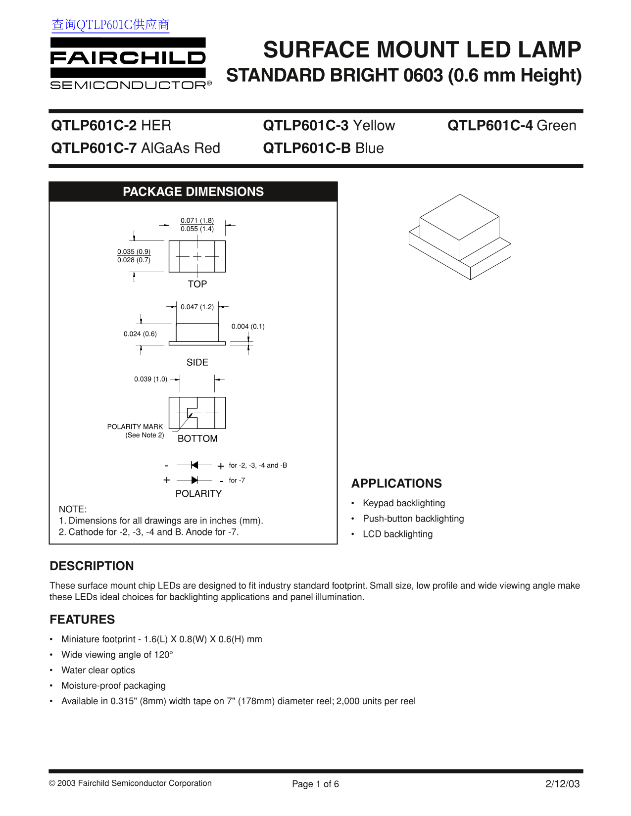
Page 1 Text Content
查询QTLP601C供应商
SURFACE MOUNT LED LAMP STANDARD BRIGHT 0603 (0.6 mm Height)
QTLP601C-2 HER QTLP601C-3 Yellow QTLP601C-4 Green QTLP601C-7 Al Ga As Red QTLP601C-B Blue
PACKAGE DIMENSIONS
POLARITY MARK (See Note 2)
- + for -2, -3, -4 and -B for -7
APPLICATIONS
POLARITY
Keypad backlighting
NOTE:
1. Dimensions for all drawings are in inches (mm). Push-button backlighting
2. Cathode for -2, -3, -4 and B. Anode for -7. LCD backlighting
DESCRIPTION These surface mount chip LEDs are designed to fit industry standard footprint. Small size, low profile and wide viewing angle make these LEDs ideal choices for backlighting applications and panel illumination.
FEATURES Miniature footprint - 1.6(L) X 0.8(W) X 0.6(H) mm Wide viewing angle of 120° Water clear optics Moisture-proof packaging Available in 0.315" (8mm) width tape on 7" (178mm) diameter reel; 2,000 units per reel
© 2003 Fairchild Semiconductor Corporation Page 1 of 6 2/12/03
Page Summary Contents For Fairchild QTLP601C-2 Data Sheet
Manual Details
| Brand | Fairchild |
|---|---|
| Pages | 6 |
| File Size | 360.20 KB |
| Published | July 07, 2026 |
Enter the captcha to get the download link:

Frequently Asked Questions
What is the typical viewing angle for these LED chips?
The QTLP601C series features a wide viewing angle of 120°.
Can I use this component in life support devices or systems?
No, Fairchild's products are not authorized for use as critical components in life support unless expressed written approval is obtained.
What information do I need regarding soldering and installation?
For optimal results, the maximum lead soldering time should be 5 seconds at 260°C, with a recommended PCB pattern provided.
Which specific QTLP601C color variant generates a 660nm peak wavelength?
The QTLP601C-7 AlGaAs red variant generates a 660 nm peak wavelength at 20mA.