Fairchild NC7WZ14 Data Handbook
Summary
This Ultra-High Speed (UHS) dual inverter integrates reliable performance with robust digital signal processing through integrated Schmitt Trigger Inputs. Designed for critical applications, this component provides both high output drive capability and ultra-fast switching speeds across a wide operating voltage range. The datasheet details every aspect required by hardware designers, covering electrical characteristics, absolute maximum ratings, various package options (SC70, MicroPak), and recommended operational guidelines for reliable system integration in speed-sensitive circuits.
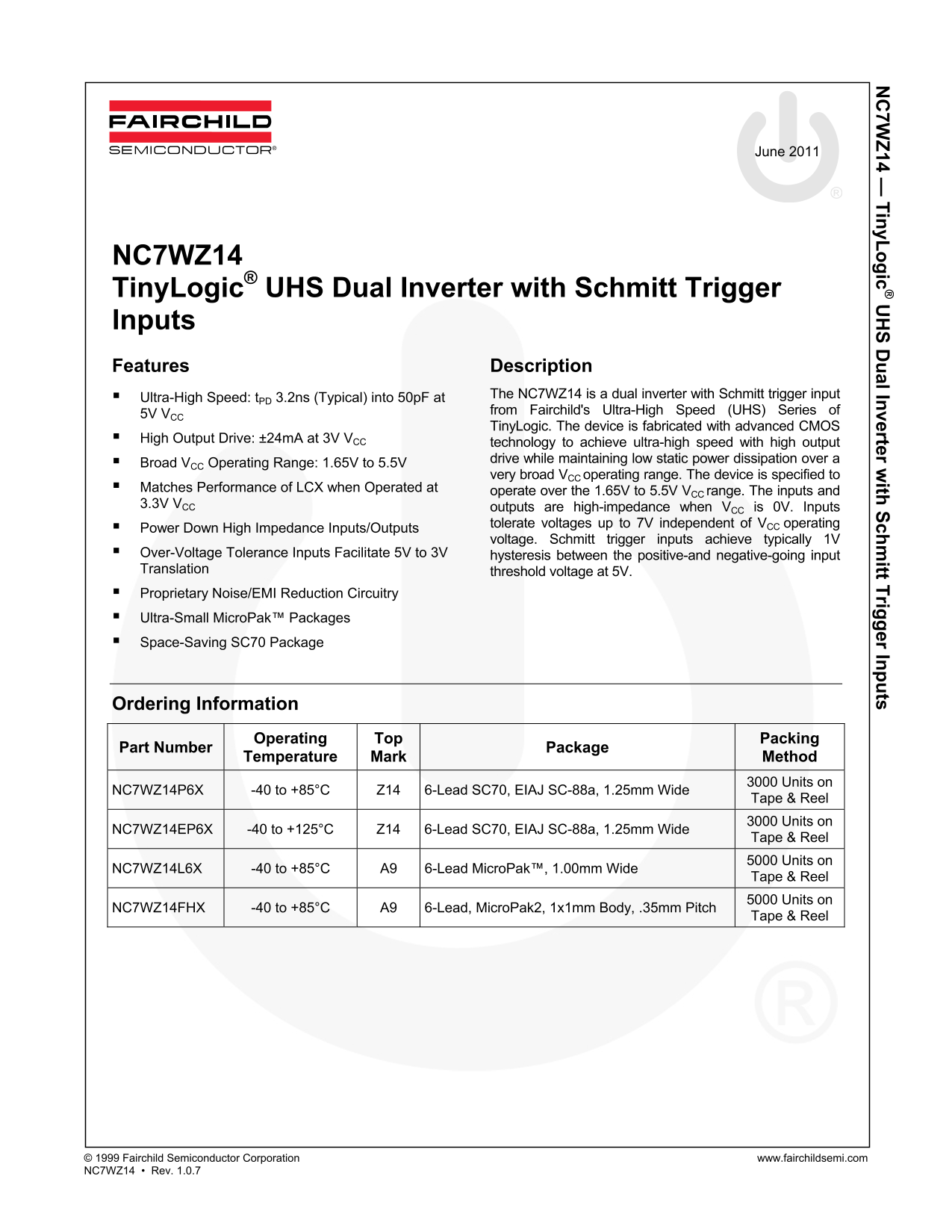
Page 1 Text Content
7W 14 — in y L ic al In verter w ith ch itt T rig er In ts
June 2011
NC7WZ14 Tiny Logic® UHS Dual Inverter with Schmitt Trigger Inputs Features Description
Ultra-High Speed: t PD 3.2ns (Typical) into 50p F at The NC7WZ14 is a dual inverter with Schmitt trigger input from Fairchild's Ultra-High Speed (UHS) Series of
5V VCC
Tiny Logic. The device is fabricated with advanced CMOS
High Output Drive: ±24m A at 3V VCC
technology to achieve ultra-high speed with high output Broad VCC Operating Range: 1.65V to 5.5V drive while maintaining low static power dissipation over a very broad VCC operating range. The device is specified to
Matches Performance of LCX when Operated at operate over the 1.65V to 5.5V VCC range. The inputs and 3.3V VCC outputs are high-impedance when VCC is 0V. Inputs
tolerate voltages up to 7V independent of VCC operating
Power Down High Impedance Inputs/Outputs
voltage. Schmitt trigger inputs achieve typically 1V
Over-Voltage Tolerance Inputs Facilitate 5V to 3V hysteresis between the positive-and negative-going input Translation threshold voltage at 5V. Proprietary Noise/EMI Reduction Circuitry Ultra-Small Micro Pak™ Packages Space-Saving SC70 Package
Ordering Information
Operating Packing
Part Number Package
Temperature Mark Method
3000 Units on
NC7WZ14P6X -40 to +85°C Z14 6-Lead SC70, EIAJ SC-88a, 1.25mm Wide
Tape & Reel 3000 Units on
NC7WZ14EP6X -40 to +125°C Z14 6-Lead SC70, EIAJ SC-88a, 1.25mm Wide
Tape & Reel 5000 Units on
NC7WZ14L6X -40 to +85°C A9 6-Lead Micro Pak™, 1.00mm Wide
Tape & Reel 5000 Units on
NC7WZ14FHX -40 to +85°C A9 6-Lead, Micro Pak2, 1x1mm Body, .35mm Pitch
Tape & Reel
© 1999 Fairchild Semiconductor Corporation www.fairchildsemi.com NC7WZ14 • Rev. 1.0.7
Page Summary Contents For Fairchild NC7WZ14 Data Handbook
Manual Details
| Brand | Fairchild |
|---|---|
| Pages | 9 |
| File Size | 518.42 KB |
| Published | July 15, 2026 |
Enter the captcha to get the download link:

Frequently Asked Questions
What is the optimal supply voltage range for the NC7WZ14?
The recommended operating range for the supply voltage (VCC) is between 1.65V and 5.50V.
How does the Schmitt trigger input function?
Schmitt trigger inputs provide a hysteresis between the positive-and negative-going input threshold voltage, achieving typically 1V at 5V.
Which packages are available for this device?
It is available in SC70 and MicroPak™ packages, including Ultra-Small MicroPak™ variants.
What happens to unused inputs or outputs?
Unused inputs must be held high or low; they may not float.