Fairchild FST32245 Data Handbook
Summary
This high-performance octal bus switch provides 8 dedicated bits of flexible switching between two ports, compatible with both CMOS and TTL logic levels. Key features include built-in 25Ω series resistors to mitigate signal reflection noise, eliminating the need for external termination components. The comprehensive manual details electrical characteristics, operating guidelines, pin assignments, and reliability parameters, making it an essential component for electronics engineers designing reliable bus switching circuits.
Page 1 Text Content
查询FST32245供应商
Preliminary
32245 O ctal B s S itch ith 25Ω eries R esisto r in tp ts (P relim in ary)
June 2001 Revised June 2001
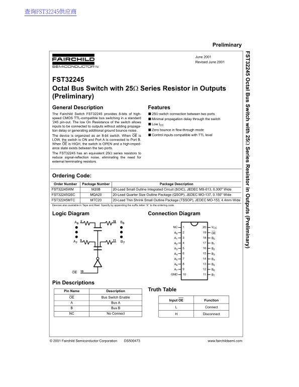
FST32245 Octal Bus Switch with 25Ω Series Resistor in Outputs (Preliminary) General Description Features The Fairchild Switch FST32245 provides 8-bits of high- ■25Ω switch connection between two ports speed CMOS TTL-compatible bus switching in a standard ■Minimal propagation delay through the switch ’245 pin-out. The low On Resistance of the switch allows
■Low l CC
inputs to be connected to outputs without adding propaga-
tion delay or generating additional ground bounce noise. ■Zero bounce in flow-through mode The device is organized as an 8-bit switch. When OE is ■Control inputs compatible with TTL level
LOW, the switch is ON and Port A is connected to Port B. When OE is HIGH, the switch is OPEN and a high-imped- ance state exists between the two ports. The FST32245 has an equivalent 25Ω series resistors to reduce signal-reflection noise, eliminating the need for external terminating resistors.
Ordering Code: Order Number Package Number Package Description FST32245WM M20B 20-Lead Small Outline Integrated Circuit (SOIC), JEDEC MS-013, 0.300" Wide FST32245QSC MQA20 20-Lead Quarter Size Outline Package (QSOP), JEDEC MO-137, 0.150" Wide FST32245MTC MTC20 20-Lead Thin Shrink Small Outline Package (TSSOP), JEDEC MO-153, 4.4mm Wide Devices also available in Tape and Reel. Specify by appending the suffix letter “X” to the ordering code.
Logic Diagram Connection Diagram
Pin Descriptions
Pin Name Description Truth Table
OE Bus Switch Enable
Input OE Function
Bus A
Bus B Connect
NC No Connect Disconnect
© 2001 Fairchild Semiconductor Corporation DS500473 www.fairchildsemi.com
Page Summary Contents For Fairchild FST32245 Data Handbook
Manual Details
| Brand | Fairchild |
|---|---|
| Pages | 5 |
| File Size | 168.70 KB |
| Published | June 16, 2026 |
Enter the captcha to get the download link:

Frequently Asked Questions
What condition is required for the FST32245 switch to activate?
The switch connects Port A to Port B when OE (Bus Switch Enable) is LOW and open when OE is HIGH.
Does the FST32245 require external resistors to minimize signal reflection?
No, it has an equivalent 25Ω series resistor in its outputs to reduce signal-reflection noise.
What are the recommended operating voltage ranges for power and input?
The power supply (VCC) should operate between 4.0V and 5.5V, while the input voltage ranges from 0V to 5.5V DC.
Are these components safe for use in life support systems?
The product is not authorized for use as critical components in life support devices without express written approval.