Fairchild FSL136HR Specifications Manual
Summary
This integrated power switch is an advanced pulse width regulator combining a SenseFET and PWM control block for efficient offline flyback converters. Designed for reliability and low component count, it handles AC inputs from 85V to 265V while featuring essential protections like Over-Voltage (OVP), Soft-Start, and Ultra-Low Standby Power (<50mW). The manual provides comprehensive technical details, including the internal circuit architecture, pin definitions, operational modes, and optimal integration guidelines. It is specifically for power supply engineers developing compact, high-performance SMPS solutions for home appliances, adapters, and various consumer electronics.
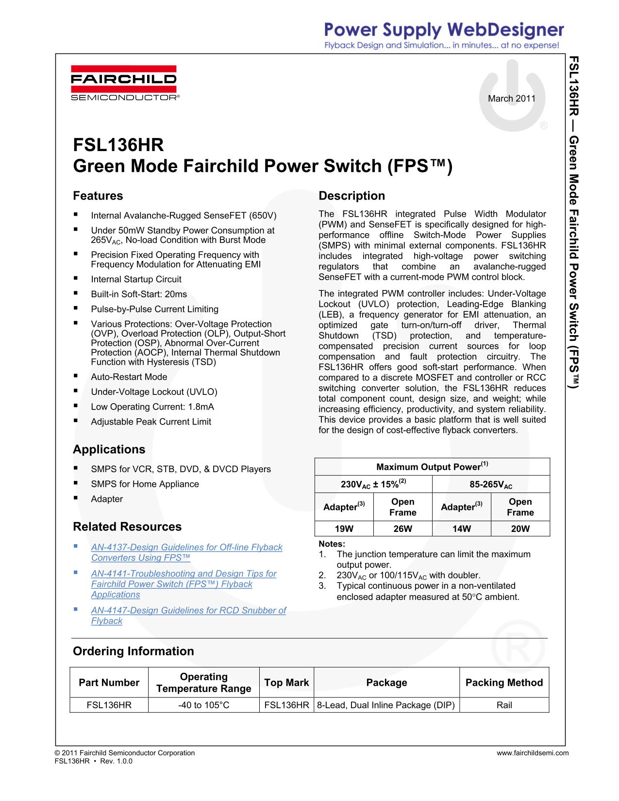
Page 1 Text Content
136H reen e F airch ild er S itch (F
March 2011
FSL136HR Green Mode Fairchild Power Switch (FPS™) Features Description
Internal Avalanche-Rugged Sense FET (650V) The FSL136HR integrated Pulse Width Modulator (PWM) and Sense FET is specifically designed for high-
Under 50m W Standby Power Consumption at
performance offline Switch-Mode Power Supplies
265VAC, No-load Condition with Burst Mode
(SMPS) with minimal external components. FSL136HR
Precision Fixed Operating Frequency with includes integrated high-voltage power switching Frequency Modulation for Attenuating EMI regulators that combine an avalanche-rugged
Internal Startup Circuit Sense FET with a current-mode PWM control block. Built-in Soft-Start: 20ms The integrated PWM controller includes: Under-Voltage Lockout (UVLO) protection, Leading-Edge Blanking
Pulse-by-Pulse Current Limiting
(LEB), a frequency generator for EMI attenuation, an
Various Protections: Over-Voltage Protection optimized gate turn-on/turn-off driver, Thermal (OVP), Overload Protection (OLP), Output-Short Shutdown (TSD) protection, and temperature- Protection (OSP), Abnormal Over-Current
compensated precision current sources for loop
Protection (AOCP), Internal Thermal Shutdown
compensation and fault protection circuitry. The
Function with Hysteresis (TSD)
FSL136HR offers good soft-start performance. When
Auto-Restart Mode compared to a discrete MOSFET and controller or RCC
switching converter solution, the FSL136HR reduces
Under-Voltage Lockout (UVLO)
total component count, design size, and weight; while
Low Operating Current: 1.8m A
increasing efficiency, productivity, and system reliability. Adjustable Peak Current Limit This device provides a basic platform that is well suited for the design of cost-effective flyback converters.
Applications
SMPS for VCR, STB, DVD, & DVCD Players Maximum Output Power(1)
SMPS for Home Appliance 230VAC ± 15%(2) 85-265VAC Adapter
Open Open
Adapter(3) Adapter(3)
Frame Frame
Related Resources 19W 26W 14W 20W
Notes:
AN-4137-Design Guidelines for Off-line Flyback
1. The junction temperature can limit the maximum
Converters Using FPS™
output power.
AN-4141-Troubleshooting and Design Tips for 2. 230VAC or 100/115VAC with doubler. Fairchild Power Switch (FPS™) Flyback 3. Typical continuous power in a non-ventilated Applications
enclosed adapter measured at 50C ambient.
AN-4147-Design Guidelines for RCD Snubber of Flyback
Ordering Information
Operating
Part Number Top Mark Package Packing Method
Temperature Range
FSL136HR -40 to 105°C FSL136HR 8-Lead, Dual Inline Package (DIP) Rail
© 2011 Fairchild Semiconductor Corporation www.fairchildsemi.com FSL136HR • Rev. 1.0.0
Page Summary Contents For Fairchild FSL136HR Specifications Manual
Manual Details
| Brand | Fairchild |
|---|---|
| Pages | 13 |
| File Size | 1.02 MB |
| Published | July 07, 2026 |
Enter the captcha to get the download link:

Frequently Asked Questions
How does the FSL136HR device generally start up?
At startup, an internal switch supplies power to charge an external storage capacitor. Once this voltage reaches 12V, the internal CC switch opens, and device power transitions to the auxiliary transformer winding.
What major protections are built into the FSL136HR PWM controller?
It includes various protections such as Over-Voltage Protection (OVP), Overload Protection (OLP), Output-Short Shutdown (OSP), temperature-Protection, Under-Voltage Lockout (UVLO), and more.
How can I adjust the peak current limit of the SenseFET?
The peak current limit is adjusted by diverting a 0.4mA current source to a combination of an internal 6kΩ resistor and an external resistor connected to ground on pin 4.
What is the standby power consumption under burst mode?
The device reports an under 50mW Standby Power Consumption at no-load condition with Burst Mode AC (SMPS).