Fairchild FSEZ1317A Data Handbook
Summary
This integrated Primary-Side-Regulation PWM controller provides highly efficient and low-power solutions for modern flyback chargers. Designed for battery management systems in portable electronics, including cell phones, PDAs, and digital cameras. The manual details advanced features like constant current/voltage regulation (CC/CV), proprietary Green-Mode operation, and robust protection circuits. Ideal for designers seeking compact, cost-effective replacements for traditional SMPS designs.
Page 1 Text Content
1317A rim ary-S id e-R eg latio ith In teg rated
May 2012
FSEZ1317A Primary-Side-Regulation PWM with POWER MOSFET Integrated Features Description
Low Standby Power Under 30m W This third-generation Primary-Side-Regulation (PSR) and highly integrated PWM controller provides several
High-Voltage Startup
features to enhance the performance of low-power Fewest External Component Counts flyback converters. The proprietary topology, TRUECURRENT®, of FSEZ1317A enables precise CC
Constant-Voltage (CV) and Constant-Current (CC)
regulation and simplified circuit design for battery-
Control without Secondary-Feedback Circuitry
charger applications. A low-cost, smaller, and lighter charger results, as compared to a conventional design
Green-Mode: Linearly Decreasing PWM Frequency
or a linear transformer.
Fixed PWM Frequency at 50k Hz with Frequency
To minimize standby power consumption, the
Hopping to Solve EMI Problem
proprietary green mode provides off-time modulation to
Cable Compensation in CV Mode
linearly decrease PWM frequency under light-load Peak-Current-Mode Control in CV Mode conditions. Green mode assists the power supply in meeting power conservation requirements.
Cycle-by-Cycle Current Limiting
By using the FSEZ1317A, a charger can be
VDD Over-Voltage Protection with Auto Restart
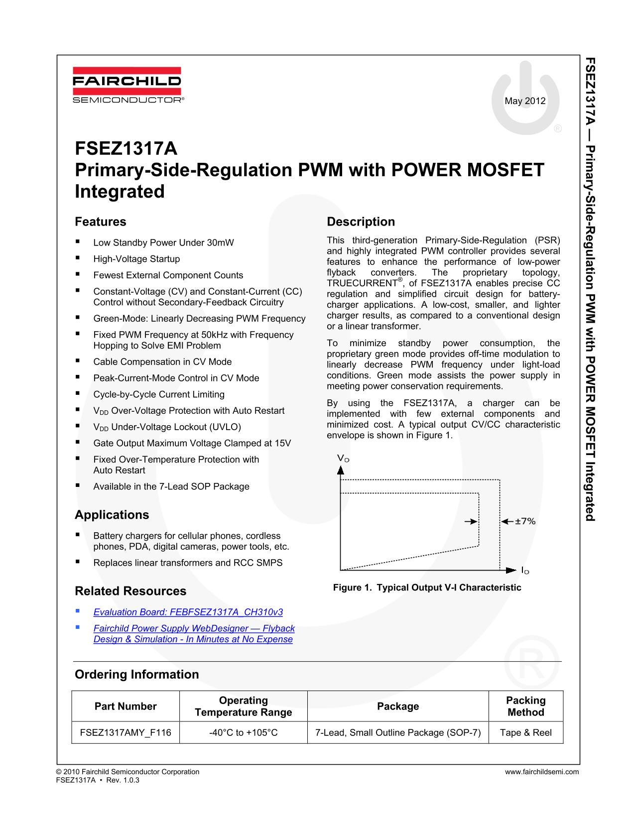
implemented with few external components and VDD Under-Voltage Lockout (UVLO) minimized cost. A typical output CV/CC characteristic envelope is shown in Figure 1.
Gate Output Maximum Voltage Clamped at 15V Fixed Over-Temperature Protection with Auto Restart Available in the 7-Lead SOP Package
Applications Battery chargers for cellular phones, cordless phones, PDA, digital cameras, power tools, etc. Replaces linear transformers and RCC SMPS
Figure 1. Typical Output V-I Characteristic
Related Resources Evaluation Board: FEBFSEZ1317A_CH310v3 Fairchild Power Supply Web Designer — Flyback Design & Simulation - In Minutes at No Expense
Ordering Information
Operating Packing
Part Number Package
Temperature Range Method
FSEZ1317AMY_F116 -40°C to +105°C 7-Lead, Small Outline Package (SOP-7) Tape & Reel
© 2010 Fairchild Semiconductor Corporation www.fairchildsemi.com FSEZ1317A • Rev. 1.0.3
Page Summary Contents For Fairchild FSEZ1317A Data Handbook
Manual Details
| Brand | Fairchild |
|---|---|
| Pages | 16 |
| File Size | 942.68 KB |
| Published | July 16, 2026 |
Enter the captcha to get the download link:

Frequently Asked Questions
What specialized regulation modes can the FSEZ1317A provide?
It enables Constant-Voltage (CV) and Constant-Current (CC) regulation, including Peak-Current-Mode Control in CV Mode.
How does the device manage standby power consumption efficiently?
It features a proprietary green mode that uses off-time modulation or frequency hopping to linearly decrease PWM output frequency under light-load conditions.
What safety features protect against abnormal voltage readings?
The device includes V Over-Voltage Protection with Auto Restart (OVPO) and an Under-Voltage Lockout (UVLO).
How is the MOSFET current monitored using this controller?
Connect a resistor to Pin 1 (CS); it detects the MOSFET current, which allows for output-current regulation in CC mode.