# A B C D E F G H I J K L M N O P Q R S T U V W X Y Z

Fairchild Fan7384 Data Handbook

Summary

The FAN7384 is a specialized half-bridge gate-drive IC designed for high-voltage, high-speed applications, including motor inverters and full-bridge power supplies up to +600V. It ensures robust operation through integrated features like shoot-through prevention, common-mode noise canceling, and UVLO protection. This manual provides engineers with comprehensive technical documentation, detailing the IC's functional block diagram, precise pinout configurations, recommended PCB layout guidelines, and crucial operating specifications for reliable system integration.
📄 Preview PAGE OF 17

Page 1 Text Content

7384 — alf-B rid e G ate-D rive IC

July 2012

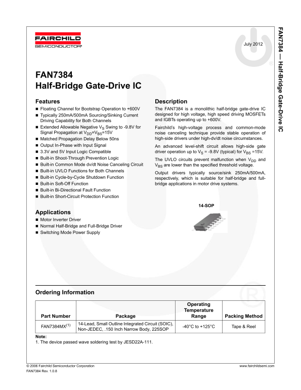
FAN7384 Half-Bridge Gate-Drive IC Features Description Floating Channel for Bootstrap Operation to +600V The FAN7384 is a monolithic half-bridge gate-drive IC

Typically 250m A/500m A Sourcing/Sinking Current designed for high voltage, high speed driving MOSFETs Driving Capability for Both Channels and IGBTs operating up to +600V.

Extended Allowable Negative VS Swing to -9.8V for Fairchild’s high-voltage process and common-mode Signal Propagation at VDD=VBS=15V noise canceling technique provide stable operation of

Matched Propagation Delay Below 50ns high-side drivers under high-dv/dt noise circumstances.

Output In-Phase with Input Signal An advanced level-shift circuit allows high-side gate 3.3V and 5V Input Logic Compatible driver operation up to VS = -9.8V (typical) for VBS =15V. Built-in Shoot-Through Prevention Logic

The UVLO circuits prevent malfunction when VDD and

Built-in Common Mode dv/dt Noise Canceling Circuit VBS are lower than the specified threshold voltage. Built-in UVLO Functions for Both Channels

Output drivers typically source/sink 250m A/500m A,

Built-in Cycle-by-Cycle Shutdown Function respectively, which is suitable for half-bridge and full- Built-in Soft-Off Function bridge applications in motor drive systems. Built-in Bi-Directional Fault Function Built-in Short-Circuit Protection Function

14-SOP

Applications Motor Inverter Driver Normal Half-Bridge and Full-Bridge Driver Switching Mode Power Supply

Ordering Information

Operating Temperature

Part Number Package Range Packing Method

14-Lead, Small Outline Integrated Circuit (SOIC),

FAN7384MX(1) -40°C to +125°C Tape & Reel

Non-JEDEC, .150 Inch Narrow Body, 225SOP

Note: 1. The device passed wave soldering test by JESD22A-111.

© 2 006 Fairchild Semiconductor Corporation www.fairchildsemi.com FAN 7384 Rev. 1.0.8

Page Summary Contents For Fairchild Fan7384 Data Handbook

Page 1 7384 — alf-B rid e G ate-D rive IC July 2012 FAN7384 Half-Bridge Gate-Drive IC Features Description Floating Channel for Bootstrap Operation to +600V The FAN7384 is a monolithic half-bridge gate-drive...
Page 2 7384 — alf-B rid e G ate-D rive IC Typical Application Diagrams VDD VDD VDD VB HO HO HO UU HIN VB UL LIN 3-Phase VU HIN VS Motor UL LIN VB Controller WU HIN WL LIN VS FO FO FO SD SD SD LO LO LO CSC CS...
Page 3 7384 — alf-B rid e G ate-D rive IC Internal Block Diagram HS(ON/OFF) NOISE IV IV CANCELLER SCHMITT TRIGGER INPUT VDD_UVLO UVLO VDD HIN SHOOT-THROUGH PREVENTION LS(ON/OFF) GND/VSL DELAY LEVEL SHIFTER 2...
Page 4 7384 — alf-B rid e G ate-D rive IC Pin Configuration LIN VB SD HO HIN VS VDD NC FO NC CSC LO GND VSL FAN7384 Rev.00 Figure 4. Pin Configuration (Top View) Pin Definitions Pin # Name Description LIN Lo...
Page 5 7384 — alf-B rid e G ate-D rive IC Absolute Maximum Ratings Stresses exceeding the absolute maximum ratings may damage the device. The device may not function or be opera- ble above the recommended op...
Page 6 7384 — alf-B rid e G ate-D rive IC Electrical Characteristics VBIAS (VDD, VBS) = 15.0V, TA = 25C, unless otherwise specified. The VIN and IIN parameters are referenced to GND. The VO and IO parameter...
Page 7 7384 — alf-B rid e G ate-D rive IC Electrical Characteristics (Continued) VBIAS (VDD, VBS) = 15.0V, TA = 25C, unless otherwise specified. The VIN and IIN parameters are referenced to GND. The VO and ...
Page 8 7384 — alf-B rid e G ate-D rive IC Typical Characteristics Temperature [°C] Temperature [°C] Figure 5. VDD UVLO (+) vs. Temperature Figure 6. VDD UVLO (-) vs. Temperature Temperature [°C] Temperature ...
Page 9 7384 — alf-B rid e G ate-D rive IC Typical Characteristics (Continued) [ IN Temperature [°C] Temperature [°C] Figure 11. VDD Quiescent Current vs. Temperature Figure 12. VBS Quiescent Current vs. Tem...
Page 10 7384 — alf-B rid e G ate-D rive IC Typical Characteristics (Continued) se c] se c] ff [n f [n Temperature [°C] Temperature [°C] Figure 17. ISOFT vs. Temperature Figure 18. Turn-on Rising Time vs. Temp...
Page 11 7384 — alf-B rid e G ate-D rive IC Typical Characteristics (Continued) [V IL Temperature [°C] Temperature [°C] Figure 23. Logic Input Low Voltage vs. Temperature Figure 24. Logic Input Hysteresis vs. ...
Page 12 7384 — alf-B rid e G ate-D rive IC Typical Characteristics (Continued) Temperature [°C] Temperature [°C] Figure 29. Fault Output High Voltage vs. Figure 30. Fault Output Low Voltage vs. Temperature Te...
Page 13 7384 — alf-B rid e G ate-D rive IC Switching Time Definitions The overall switching timing waveforms definition of FAN7384 as shown Figure 33. Low-Side Output Shutdown Low-Side Output Disable Disable ...
Page 14 7384 — alf-B rid e G ate-D rive IC Typical Application Information 1. Protection Function HIN/LIN 1.1 Under-Voltage Lockout (UVLO) The high- and low-side drivers include under-voltage lockout (UVLO) p...
Page 15 7384 — alf-B rid e G ate-D rive IC 2. Layout Considerations 2.2 Gate-Drive Loop For optimum performance, considerations must be taken Current loops behave like antennae, able to receive and during pri...
Page 16 7384 — alf-B rid e G ate-D rive IC Package Dimensions Figure 38. 14-Lead, Small Outline Integrated Circuit (SOIC), Non-JEDEC, .150 Inch Narrow Body, 225SOP Package drawings are provided as a service t...
Page 17 7384 — alf-B rid e G ate-D rive IC © 2 006 Fairchild Semiconductor Corporation www.fairchildsemi.com FAN 7384 Rev. 1.0.8 17

Manual Details

Brand Fairchild
Pages 17
File Size 695.42 KB
Published June 20, 2026
1 views

Enter the captcha to get the download link:

captcha

Frequently Asked Questions

What is the maximum operating voltage for the FAN7384 IC?

The device is designed for MOSFETs and IGBTs capable of operating up to +600V, while also supporting 3.3V and 5V input logic levels.

Which built-in protective features does the chip offer?

It includes Shoot-Through Prevention Logic, UVLO circuits for both channels, Short-Circuit Protection, Soft-Off functions, and a Common Mode dv/dt Noise Canceling Circuit.

What layout guidelines must be followed for optimum performance?

Gate-drive loops must be minimized during PCB layout, and the ground plane should be placed under or near the high-voltage floating side to minimize noise coupling.