Fairchild Fan6755W Data Handbook
Summary
Optimize your power supplies with this highly integrated mWSaver™ PWM Controller, engineered specifically for performance-critical flyback converters. Utilizing proprietary technology, it achieves industry-leading energy efficiency, keeping standby consumption under 100mW while meeting global standards. Ideal for powering LCD monitors and open-frame SMPS, the controller provides robust protection (OVP, OTP, OLP) and advanced control stability. Reference this guide for detailed technical specifications, integration details, and operational features.
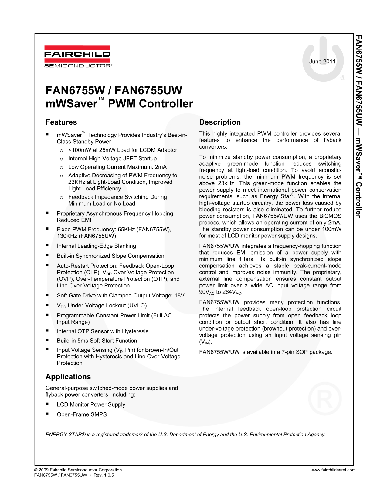
Page 1 Text Content
6755W / F 6755U aver™ tro ller
June 2011
FAN6755W / FAN6755UW m WSaver™ PWM Controller Features Description
m WSaver™ Technology Provides Industry’s Best-in- This highly integrated PWM controller provides several features to enhance the performance of flyback
Class Standby Power
converters.
o <100m W at 25m W Load for LCDM Adaptor
To minimize standby power consumption, a proprietary
o Internal High-Voltage JFET Startup
adaptive green-mode function reduces switching
o Low Operating Current Maximum: 2m A
frequency at light-load condition. To avoid acoustic-
o Adaptive Decreasing of PWM Frequency to noise problems, the minimum PWM frequency is set 23KHz at Light-Load Condition, Improved above 23k Hz. This green-mode function enables the Light-Load Efficiency power supply to meet international power conservation
o Feedback Impedance Switching During requirements, such as Energy Star®. With the internal Minimum Load or No Load high-voltage startup circuitry, the power loss caused by bleeding resistors is also eliminated. To further reduce
Proprietary Asynchronous Frequency Hopping
power consumption, FAN6755W/UW uses the Bi CMOS
Reduced EMI
process, which allows an operating current of only 2m A. Fixed PWM Frequency: 65KHz (FAN6755W), The standby power consumption can be under 100m W 130KHz (FAN6755UW) for most of LCD monitor power supply designs.
Internal Leading-Edge Blanking FAN6755W/UW integrates a frequency-hopping function
that reduces EMI emission of a power supply with
Built-in Synchronized Slope Compensation
minimum line filters. Its built-in synchronized slope Auto-Restart Protection: Feedback Open-Loop compensation achieves a stable peak-current-mode Protection (OLP), VDD Over-Voltage Protection control and improves noise immunity. The proprietary, (OVP), Over-Temperature Protection (OTP), and external line compensation ensures constant output Line Over-Voltage Protection power limit over a wide AC input voltage range from 90VAC to 264VAC.
Soft Gate Drive with Clamped Output Voltage: 18V
FAN6755W/UW provides many protection functions.
VDD Under-Voltage Lockout (UVLO)
The internal feedback open-loop protection circuit Programmable Constant Power Limit (Full AC protects the power supply from open feedback loop Input Range) condition or output short condition. It also has line under-voltage protection (brownout protection) and over-
Internal OTP Sensor with Hysteresis
voltage protection using an input voltage sensing pin
Build-in 5ms Soft-Start Function (VIN). Input Voltage Sensing (VIN Pin) for Brown-In/Out
FAN6755W/UW is available in a 7-pin SOP package.
Protection with Hysteresis and Line Over-Voltage Protection
Applications General-purpose switched-mode power supplies and flyback power converters, including: LCD Monitor Power Supply Open-Frame SMPS
ENERGY STAR® is a registered trademark of the U.S. Department of Energy and the U.S. Environmental Protection Agency.
© 2009 Fairchild Semiconductor Corporation www.fairchildsemi.com FAN6755W / FAN6755UW • Rev. 1.0.5
Page Summary Contents For Fairchild Fan6755W Data Handbook
Manual Details
| Brand | Fairchild |
|---|---|
| Pages | 17 |
| File Size | 939.48 KB |
| Published | July 07, 2026 |
Enter the captcha to get the download link:

Frequently Asked Questions
What material standard is the chip package?
The device comes in a 7-pin Small Outline Package (SOP).
What are the standby power consumption benefits?
Standby power can be under 100mW, which helps meet international standards like Energy Star.
What protection circuits does this controller include?
It includes multiple protections: OLP, OVP, OTP, UVLO, and over-voltage/under-voltage detection.
What are the two different operating frequencies available?
The FAN6755W model operates at 65KHz, while the FAN6755UW model operates at 130KHz.