Fairchild FAN6751MR Data Handbook
Summary
Datasheet for Fairchild FAN6751MR highly-integrated Green-Mode PWM controller providing multiple features to enhance flyback converter performance. Features high-voltage startup circuitry eliminating power loss from bleeding resistors, proprietary green-mode function with linearly decreasing PWM frequency at light-load conditions (minimum 18kHz to avoid acoustic-noise problems), and built-in synchronized slope compensation for stable peak-current-mode control. External line compensation ensures
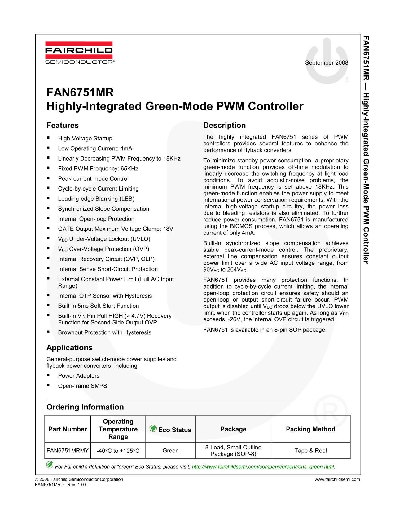
Page 1 Text Content
FA 6751M ighly-Integrated G reen-M ode PW ontroller
September 2008
FAN6751MR Highly-Integrated Green-Mode PWM Controller Features Description
High-Voltage Startup The highly integrated FAN6751 series of PWM controllers provides several features to enhance the
Low Operating Current: 4m A
performance of flyback converters.
Linearly Decreasing PWM Frequency to 18KHz
To minimize standby power consumption, a proprietary Fixed PWM Frequency: 65KHz green-mode function provides off-time modulation to linearly decrease the switching frequency at light-load
Peak-current-mode Control
conditions. To avoid acoustic-noise problems, the minimum PWM frequency is set above 18KHz. This
Cycle-by-cycle Current Limiting
green-mode function enables the power supply to meet
Leading-edge Blanking (LEB) international power conservation requirements. With the
internal high-voltage startup circuitry, the power loss
Synchronized Slope Compensation
due to bleeding resistors is also eliminated. To further
Internal Open-loop Protection reduce power consumption, FAN6751 is manufactured
using the Bi CMOS process, which allows an operating
GATE Output Maximum Voltage Clamp: 18V
current of only 4m A.
VDD Under-Voltage Lockout (UVLO)
Built-in synchronized slope compensation achieves
VDD Over-Voltage Protection (OVP) stable peak-current-mode control. The proprietary,
external line compensation ensures constant output
Internal Recovery Circuit (OVP, OLP)
power limit over a wide AC input voltage range, from
Internal Sense Short-Circuit Protection 90VAC to 264VAC. External Constant Power Limit (Full AC Input FAN6751 provides many protection functions. In Range) addition to cycle-by-cycle current limiting, the internal
open-loop protection circuit ensures safety should an
Internal OTP Sensor with Hysteresis
open-loop or output short-circuit failure occur. PWM
Built-in 5ms Soft-Start Function output is disabled until VDD drops below the UVLO lower
limit, when the controller starts up again. As long as VDD
Built-in VIN Pin Pull HIGH (> 4.7V) Recovery
exceeds ~26V, the internal OVP circuit is triggered.
Function for Second-Side Output OVP
FAN6751 is available in an 8-pin SOP package.
Brownout Protection with Hysteresis
Applications General-purpose switch-mode power supplies and flyback power converters, including: Power Adapters Open-frame SMPS
Ordering Information
Operating
Part Number Temperature Eco Status Package Packing Method
Range
FAN6751MRMY -40°C to +105°C Green 8-Lead, Small Outline
Package (SOP-8) Tape & Reel
For Fairchild’s definition of “green” Eco Status, please visit: http://www.fairchildsemi.com/company/green/rohs_green.html.
© 2008 Fairchild Semiconductor Corporation www.fairchildsemi.com FAN6751MR • Rev. 1.0.0
Page Summary Contents For Fairchild FAN6751MR Data Handbook
Manual Details
| Brand | Fairchild |
|---|---|
| Pages | 13 |
| File Size | 462.95 KB |
| Published | July 07, 2026 |
Enter the captcha to get the download link:

Frequently Asked Questions
What are the primary protection functions of the FAN6751 controller?
It includes Open-loop Protection, Internal OTP Sensor with Hysteresis, Brownout Detection, and built-in Soft-Start functionality.
How does the device conserve power in a standby state?
A proprietary green-mode function enables linearly decreasing PWM frequency down to 18KHz to minimize standby power consumption.
What is the operating current characteristic of the FAN6751?
It maintains a low operating current of only 4mA through its operation.
Where should I connect external compensation signals and how does it affect PWM duty cycle?
The external compensation circuit signal connects to Pin 1 (GND) and determines the PWM duty cycle in response to this signal and the SENSE pin reading.