# A B C D E F G H I J K L M N O P Q R S T U V W X Y Z

Fairchild FAN5091 Specifications manual

Summary

This advanced two-slice synchronous buck converter controller provides precise, high-efficiency power regulation for demanding applications. Featuring a highly programmable output voltage and built-in current sharing, it delivers exceptional transient response crucial for modern high-performance processors like CPUs. The manual details its integration of remote sensing, various protection modes, and adaptability to complex power supply designs, making it essential for hardware engineers building stable Voltage Regulator Modules (VRMs) requiring microvolt accuracy and reliable load handling up to 50A.
📄 Preview PAGE OF 21

Page 1 Text Content

www.fairchildsemi.com

FAN5091 Two Slice Interleaved Synchronous Buck Converter

Features Description Programmable output from 1.10V to 1.85V in 25m V steps The FAN5091 is a synchronous multi-slice DC-DC controller using an integrated 5-bit DAC IC which provides a highly accurate, programmable output Two interleaved synchronous slices for maximum voltage for all high-performance processors. Two interleaved performance synchronous buck regulator slices with built-in current shar- 100nsec response time ing operate 180° out of phase to provide the fast transient Built-in current sharing between slices response needed to satisfy high current applications while Remote sense minimizing external components. The FAN5091 features

Programmable Active Droop (Voltage Positioning) remote voltage sensing and Programmable Active Droop

Programmable frequency from 200KHz to 2MHz for 100nsec converter transient response with minimum out- Adaptive delay gate switching put capacitance. It has integrated high-current gate drivers, Integrated high-current gate drivers with adaptive delay gate switching, eliminating the need for Integrated Power Good, OV, UV, Enable/Soft Start external drive devices. The FAN5091 uses a 5-bit D/A con- functions verter to program the output voltage from 1.10V to 1.85V in Drives N-channel MOSFETs 25m V steps with an accuracy of 1%. The FAN5091 uses a Operation optimized for 5V operation high level of integration to deliver load currents in excess of High efficiency mode (E*) at light load 50A from a 5V source with minimal external circuitry. The Overcurrent protection using MOSFET sensing FAN5091 also offers integrated functions including Power 24 pin TSSOP package Good, Output Enable/Soft Start, under- voltage lockout,

over-voltage protection, and adjustable current limiting with independent current sense on each slice. It is available in a

Applications

24 pin TSSOP package.

Power supply for Pentium IV Power supply for Athlon VRM for Pentium IV processor Programmable step-down power supply

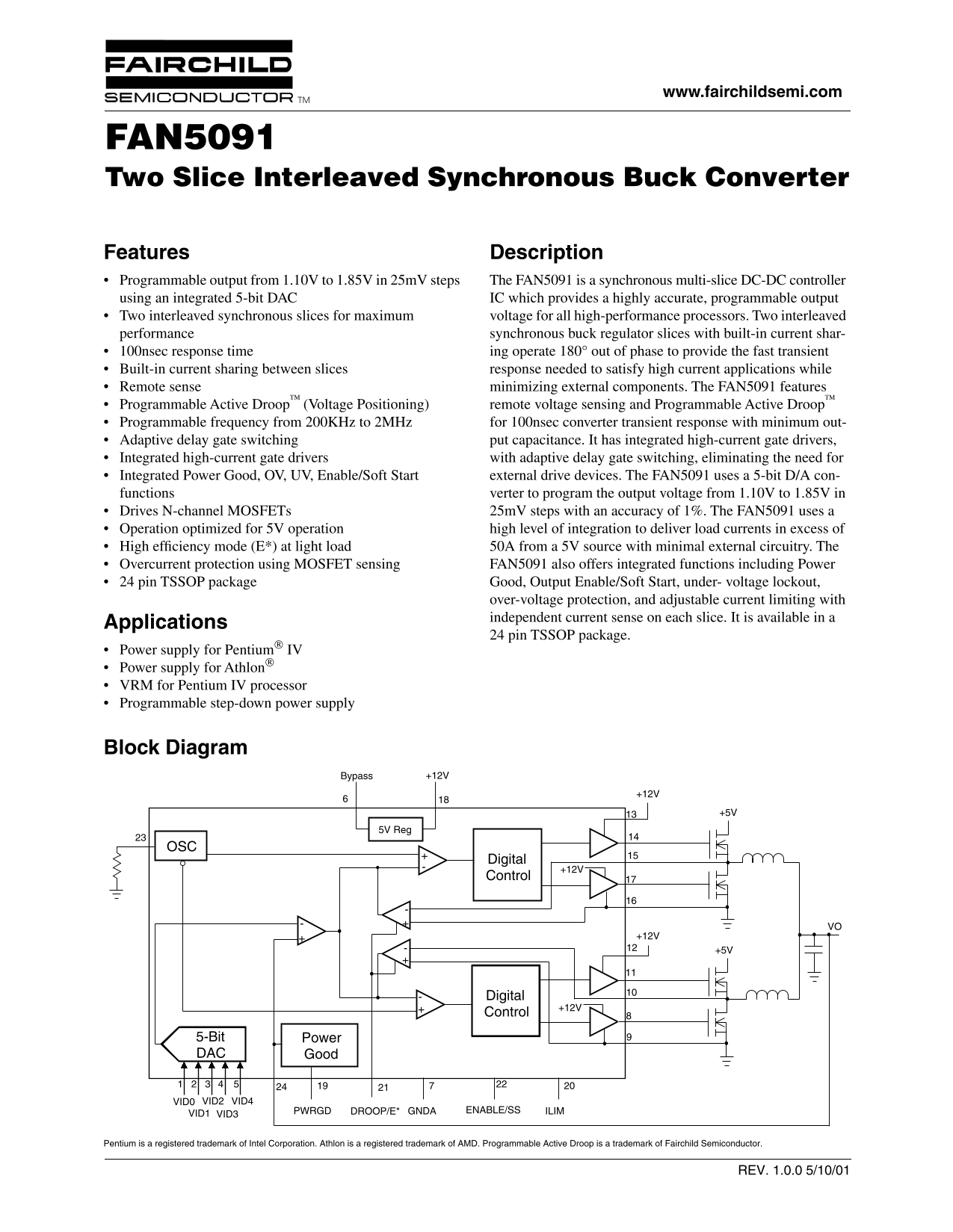
Block Diagram

Bypass +12V

5V Reg

Digital

Control

Digital

Control

5-Bit Power DAC Good

2 3 VID0 VID2 VID4

PWRGD DROOP/E* GNDA ENABLE/SS ILIM

VID1 VID3

Pentium is a registered trademark of Intel Corporation. Athlon is a registered trademark of AMD. Programmable Active Droop is a trademark of Fairchild Semiconductor.

REV. 1.0.0 5/10/01

Page Summary Contents For Fairchild FAN5091 Specifications manual

Page 1 www.fairchildsemi.com FAN5091 Two Slice Interleaved Synchronous Buck Converter Features Description Programmable output from 1.10V to 1.85V in 25m V steps The FAN5091 is a synchronous multi-slice DC-D...
Page 2 FAN5091 PRODUCT SPECIFICATION Pin Assignments VID0 VFB VID1 RT VID2 ENABLE/SS VID3 DROOP/E* VID4 ILIM BYPASS PWRGD FAN5091 AGND VCC LDRVB LDRVA PGNDB PGNDA SWB SWA HDRVB HDRVA BOOTB BOOTA Pin Definiti...
Page 3 PRODUCT SPECIFICATION FAN5091 Pin Number Pin Name Pin Function Description ILIM Current Limit. A resistor from this pin to ground sets the over current trip level. DROOP/E* Droop Control/Energy Star M...
Page 4 FAN5091 PRODUCT SPECIFICATION Electrical Specifications (V CC = 12V,V OUT = 1.500V, and T = +25°C using circuit in Figure 1, unless otherwise noted.) The denotes specifications which apply over the fu...
Page 5 PRODUCT SPECIFICATION FAN5091 Notes: 1. Steady State Voltage Regulation includes Initial Voltage Setpoint, Output Ripple and Output Temperature Drift and is measured at the converter’s VFB sense point...
Page 6 FAN5091 PRODUCT SPECIFICATION Typical Operating Characteristics 5V /D IV IS IO IV (VCC = 12V, and TA = +25°C using circuit in Figure 2, unless otherwise noted.) EFFICIENCY VS. OUTPUT CURRENT 2-Slice E...
Page 7 PRODUCT SPECIFICATION FAN5091 Typical Operating Characteristics (Continued) 5A /D IV IS IO 5V /D IV IS IO /D IV IS IO OUTPUT RIPPLE VOLTAGE GATE DRIVE RISE TIME TIME (1µs/DIVISION) TIME (50ns/DIVISION...
Page 8 FAN5091 PRODUCT SPECIFICATION Typical Operating Characteristics (Continued) ro Droop vs. RDroop (RT = 25KΩ) VOUT TEMPERATURE VARIATION RDroop (KΩ) TEMPERATURE (°C) Application Circuit L1 (Optional) VI...
Page 9 PRODUCT SPECIFICATION FAN5091 Table 2. FAN5091 Application Bill of Materials for Figure 1 Reference Manufacturer Part # Quantity Description Requirements/Comments C1-3 Panasonic 100n F, 50V Capacitor ...
Page 10 FAN5091 PRODUCT SPECIFICATION L1 (Optional) CIN +5V VID4 Q2 VID3 VID2 VID1 VID0 R8 U1 VO FAN5091 ENABLE/SS R2 R9 PWRGD Figure 2. Application Circuit for 69A Willamette Low-Frequency Application (200KH...
Page 11 PRODUCT SPECIFICATION FAN5091 Table 3. FAN5091 Application Bill of Materials for Figure 2 Reference Manufacturer Part # Quantity Description Requirements/Comments C1-3 Panasonic 100n F, 50V Capacitor ...
Page 12 FAN5091 PRODUCT SPECIFICATION L1 (Optional) VID4 Q2 D1 VID3 VID2 VID1 VID0 U1 VO FAN5091 ENABLE/SS R2 R8 PWRGD Figure 3. Application Circuit for 35A High-Frequency Application (1MHz each slice) REV. 1...
Page 13 PRODUCT SPECIFICATION FAN5091 Table 4. FAN5091 Application Bill of Materials for Figure 3 Reference Manufacturer Part # Quantity Description Requirements/Comments C1-3 Panasonic 100n F, 50V Capacitor ...
Page 14 FAN5091 PRODUCT SPECIFICATION Application Information The digital control block takes the analog comparator input to provide the appropriate pulses to the HDRV and LDRV output pins for each slice. The...
Page 15 PRODUCT SPECIFICATION FAN5091 its on-time. Each slice has its own power ground pin, to per- = 47A. [Note that this current limit level can be as high as mit the slices to be placed in different locati...
Page 16 FAN5091 PRODUCT SPECIFICATION BYPASS Reference The oscillator generates two internal sawtooth ramps, each at one-half the oscillator frequency, and running 180° out of The internal logic of the FAN509...
Page 17 PRODUCT SPECIFICATION FAN5091 Thermal Design Considerations Gate Resistors Because of the very large gate capacitances that the Use of a gate resistor on every MOSFET is mandatory. The FAN5091 may be ...
Page 18 FAN5091 PRODUCT SPECIFICATION f = DC/DC converter switching frequency The most commonly used choice for output bulk capacitors ESR = Equivalent series resistance of all output capacitors in is aluminu...
Page 19 PRODUCT SPECIFICATION FAN5091 PCB Layout Guidelines PC Motherboard Sample Layout and Gerber File A reference design for motherboard implementation of the Placement of the MOSFETs relative to the FAN50...
Page 20 FAN5091 PRODUCT SPECIFICATION Mechanical Dimensions – 24 Lead TSSOP Notes: Inches Millimeters Symbol Notes 1. Dimensioning and tolerancing per ANSI Y14.5M-1982. Min. Max. Min. Max. 2. "D" an...
Page 21 FAN5091 PRODUCT SPECIFICATION Ordering Information Product Number Description Package FAN5091MTC 5V 24 pin TSSOP DISCLAIMER FAIRCHILD SEMICONDUCTOR RESERVES THE RIGHT TO MAKE CHANGES WITHOUT FURTHER N...

Manual Details

Brand Fairchild
Pages 21
File Size 193.41 KB
Published July 16, 2026
2 views

Enter the captcha to get the download link:

captcha

Frequently Asked Questions

How is the output voltage programmed and monitored?

The voltage can be set from 1.10V to 1.85V in 25mV steps using the five VID pins, and the status is monitored via the PWRGD pin.

What connections are necessary for safe system ground?

AGND (Pin 7) should connect to a low impedance system ground plane, while PGNDA (Pin 16) must connect directly to the low-side MOSFET source.

How does the device handle high current loads?

It features two interleaved synchronous slices with built-in current sharing, maximizing voltage for high-performance processors and supporting load currents in excess of 50A.

What is the transient response time?

With a programmed frequency range of 200KHz to 2MHz, the controller achieves a fast 100nsec converter transient response.