Fairchild Fan21SV06 Data Handbook
Summary
Maximize efficiency in compact designs with this integrated synchronous buck regulator, featuring a robust 6A output capacity and single-input operation from 3V to 24V. This highly efficient device supports programmable frequency control and external clock synchronization for complex power architecture demands. The manual provides technical guides, block diagrams, and recommended PCB layouts crucial for designers tackling point-of-load applications in servers, graphics cards, high-end computing systems, and set-top boxes requiring reliable power management.
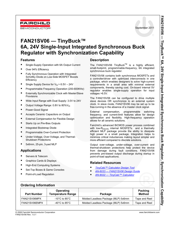
Page 1 Text Content
21S 06 — in y B ck™ 6A , 24V in le-In t In teg rated yn ch ro s B ck R eg lato r, S yn ch ro izatio ap ab ility
September 2011
FAN21SV06 — Tiny Buck™ 6A, 24V Single-Input Integrated Synchronous Buck Regulator with Synchronization Capability Features Description Single-Supply Operation with 6A Output Current The FAN210SV06 Tiny Buck TM is a highly efficient,
small-footprint, programmable-frequency, 6A integrated
Over 94% Efficiency
synchronous buck regulator.
Fully Synchronous Operation with Integrated
FAN21SV06 contains both synchronous MOSFETs and
Schottky Diode on Low-Side MOSFET Boosts
a controller/driver with optimized interconnects in one
Efficiency
package, which enables designers to solve high-current
Single Supply Device for VIN > 6.5V – 24V requirements in a small area with minimal external
components, thereby saving cost. On-board internal 5V
Programmable Frequency Operation (200-600KHz)
regulator enables single-supply operation for input
Externally Synchronizable Clock with Master/Slave voltages >6.5V. Provisions
The FAN21SV06 can be configured to drive multiple
Wide Input Range with Dual Supply: 3.0V to 24V slave devices OR synchronize to an external system
clock. In slave mode, FAN21SV06 may be set up to be
Output Voltage Range: 0.8V to 80%VIN
free-running in the absence of a master clock signal.
Power-Good Signal
External compensation, programmable switching
Accepts Ceramic Capacitors on Output frequency, and current-limit features allow for design
optimization and flexibility. High-frequency operation
External Compensation for Flexible Design
allows for all ceramic solutions.
Starts Up on Pre-Bias Outputs
Fairchild’s advanced Bi CMOS power process combined
Integrated Bootstrap Diode with low-RDS(ON) internal MOSFETs and a thermally
efficient MLP package provide the ability to dissipate
Programmable Over-Current Protection
high power in a small package. Integration helps to
Under-Voltage, Over-Voltage, and Thermal- minimize critical inductances making layout simpler and Shutdown Protections more efficient compared to discrete solutions. 5x6mm, 25-pin, 3-pad MLP Output over-voltage, under-voltage, over-current and
thermal-shutdown protections help protect the device Applications from damage during fault conditions. FAN21SV06 prevents pre-biased output discharge during startup in
Servers & Telecom point-of-load applications. Graphics Cards & Displays
Related Resources
High-End Computing Systems
Tiny Calc™ Calculator Design Tool
Set-Top Boxes & Game Consoles
AN-6033 — FAN21SV06 Design Guide
Point-of-Load Regulation AN-8022 — Tiny Calc™ Calculator
Ordering Information
Operating Packing
Part Number Temperature Range Package Method FAN21SV06MPX -10°C to 85°C Molded Leadless Package (MLP) 5x6mm Tape and Reel FAN21SV06EMPX -40°C to 85°C Molded Leadless Package (MLP) 5x6mm Tape and Reel
© 2006 Fairchild Semiconductor Corporation www.fairchildsemi.com FAN21SV06 Rev. 1.0.1
Page Summary Contents For Fairchild Fan21SV06 Data Handbook
Manual Details
| Brand | Fairchild |
|---|---|
| Pages | 17 |
| File Size | 1.19 MB |
| Published | June 18, 2026 |
Enter the captcha to get the download link:

Frequently Asked Questions
What is the maximum typical output current rating?
The FAN21SV06 is rated for a 6A output current.
Are there protections built into the device against faults?
Yes, it includes integrated over-current, under-voltage, over-voltage, and thermal-shutdown protections.
Does this regulator support single power source operation?
It supports single supply operation for input voltages greater than 6.5V up to 24V.
How can the device be configured if no master clock signal is available?
The unit can operate in free-running mode when running without an external master clock signal.