Fairchild AN-8025 Specifications Manual
Summary
Design guidelines for a 75W single-stage flyback AC-DC converter tailored for LED lighting. This application note details the implementation using the FAN7530 PFC controller, focusing on power factor correction in universal-input environments (85-265V AC). The resource covers critical design considerations, including optimal constant current (CC) control mode usage, CV/CC feedback operation, and balancing component trade-offs like MOSFET and diode selection based on transformer turns ratios. Ideal for electrical engineers designing high-efficiency, reliable power sources for LED systems.
Page 1 Text Content
www.fairchildsemi.com
AN-8025 Design Guideline of Single-Stage Flyback AC-DC Converter Using FAN7530 for LED Lighting
output should be controlled by CC mode in the normal state
Summary
while CV mode only works as over voltage protection.
This application note describes the single-stage power factor correction (PFC) and presents the design guidelines of a 75W universal-input, single-stage PFC for LED lighting applications. Flyback converter topology controlled by the critical conduction mode control IC, FAN7530 is applied and several functions; such as CV/CC mode feedback circuits, cycle-by-cycle current limit, soft-starting function, and so on, are considered for LED lighting applications.
Introduction
Figure 2. Flyback AC-DC Converter
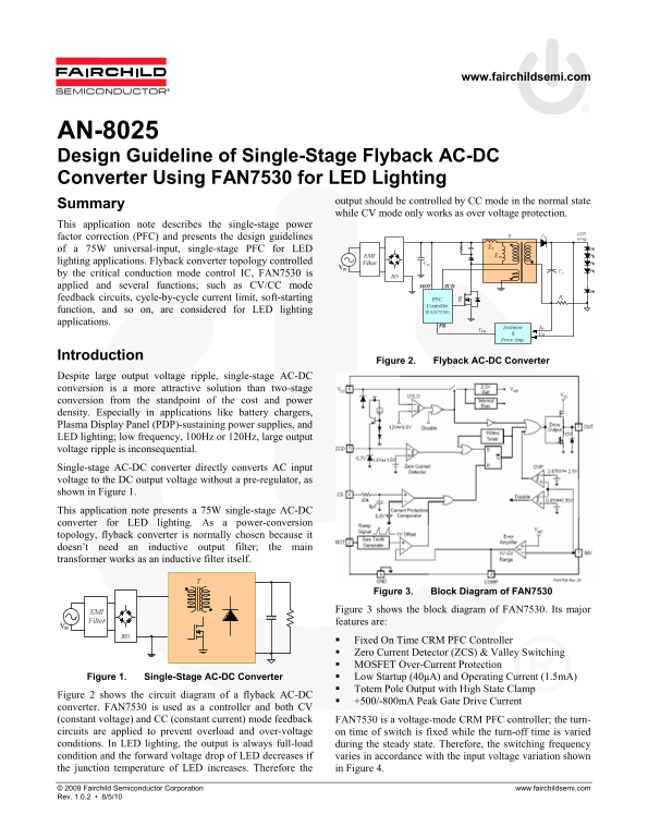
Despite large output voltage ripple, single-stage AC-DC conversion is a more attractive solution than two-stage conversion from the standpoint of the cost and power density. Especially in applications like battery chargers, Plasma Display Panel (PDP)-sustaining power supplies, and LED lighting; low frequency, 100Hz or 120Hz, large output voltage ripple is inconsequential. Single-stage AC-DC converter directly converts AC input voltage to the DC output voltage without a pre-regulator, as shown in Figure 1. This application note presents a 75W single-stage AC-DC converter for LED lighting. As a power-conversion topology, flyback converter is normally chosen because it doesn’t need an inductive output filter; the main transformer works as an inductive filter itself.
Figure 3. Block Diagram of FAN7530
Figure 3 shows the block diagram of FAN7530. Its major features are: Fixed On Time CRM PFC Controller Zero Current Detector (ZCS) & Valley Switching MOSFET Over-Current Protection Figure 1. Single-Stage AC-DC Converter Low Startup (40μA) and Operating Current (1.5m A) Totem Pole Output with High State Clamp
Figure 2 shows the circuit diagram of a flyback AC-DC
+500/-800m A Peak Gate Drive Current
converter. FAN7530 is used as a controller and both CV (constant voltage) and CC (constant current) mode feedback FAN7530 is a voltage-mode CRM PFC controller; the turn- circuits are applied to prevent overload and over-voltage on time of switch is fixed while the turn-off time is varied conditions. In LED lighting, the output is always full-load during the steady state. Therefore, the switching frequency condition and the forward voltage drop of LED decreases if varies in accordance with the input voltage variation shown the junction temperature of LED increases. Therefore the in Figure 4.
© 2009 Fairchild Semiconductor Corporation www.fairchildsemi.com Rev. 1.0.2 • 8/5/10
Page Summary Contents For Fairchild AN-8025 Specifications Manual
Manual Details
| Brand | Fairchild |
|---|---|
| Pages | 9 |
| File Size | 672.78 KB |
| Published | June 03, 2026 |
Enter the captcha to get the download link:

Frequently Asked Questions
What type of converter topology is described for LED lighting?
It uses a single-stage flyback converter topology for cost and power density benefits.
How should the output be controlled in normal operation for LED lighting?
The LED output should be controlled by CC (constant current) mode; CV (constant voltage) mode is only used for over voltage protection.
What key features does the FAN7530 PFC Controller offer?
It provides a Fixed On Time CRM PFC Controller, Zero Current Detector (ZCS), Valley Switching, and MOSFET Over-Current Protection.
What trade-off exists regarding component selection in this converter design?
There is a trade-off between the drain-to-source voltage rating ($V_{DSS}$) of the MOSFET and the reverse voltage rating ($V_{RRS}$) of the Fast Recover Diode, based on the transformer's turn ratio.