Fairchild AN-6208 Specifications Manual
Summary
The FAN6208 is an optimized secondary synchronous rectifier controller designed specifically for high-efficiency isolated LLC and LC resonant power converters. This application note guides engineers through the seamless integration of synchronous rectification, drastically improving overall system efficiency—especially under light load conditions, while preventing shoot-through. The manual provides detailed design procedures, a full half-bridge circuit example, key timing diagrams, and operational guidelines for optimal performance across varying loads and frequencies.
Page 1 Text Content
www.fairchildsemi.com
AN-6208 Secondary-Side Synchronous Rectifier (SR) for LLC Resonant Converter Using FAN6208
FAN6208 is a synchronous rectification controller for
Introduction
isolated LLC or LC resonant converters that can drive two
The LLC resonant converter has drawn a lot of attention individual SR MOSFETs emulating the behavior of rectifier recently due to its advantages over a conventional series diodes. FAN6208 measures the SR conduction time of each resonant converter and parallel resonant converter: narrow switching cycle by monitoring the drain-to-source voltage of frequency variation over wide load, input variation, and each SR and determines the optimal timing of SR gate Zero Voltage Switching (ZVS) for the entire load range. drive. FAN6208 also uses the change of opto-coupler diode
current to adaptively shrink the duration of SR gate drive
In an LLC resonant converter, rectifier diodes are typically
signals during load transients to prevent shoot-through. To
used to obtain DC output voltage from the transformer
improve light-load efficiency, Green Mode disables the SR
secondary winding. The conduction loss of diode rectifier
drive signals, minimizing gate drive power consumption at
contributes significantly to the overall power losses in an
light-load conditions.
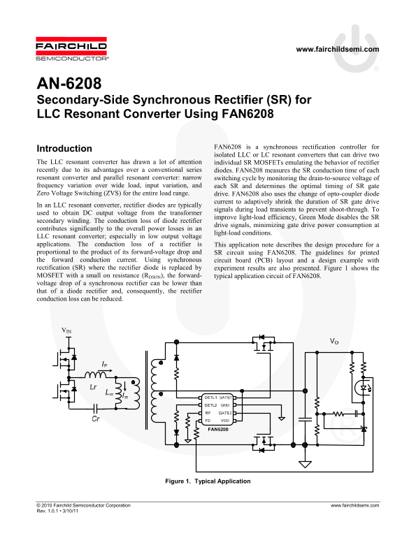
LLC resonant converter; especially in low output voltage applications. The conduction loss of a rectifier is This application note describes the design procedure for a proportional to the product of its forward-voltage drop and SR circuit using FAN6208. The guidelines for printed the forward conduction current. Using synchronous circuit board (PCB) layout and a design example with rectification (SR) where the rectifier diode is replaced by experiment results are also presented. Figure 1 shows the MOSFET with a small on resistance (RDSON), the forward- typical application circuit of FAN6208. voltage drop of a synchronous rectifier can be lower than that of a diode rectifier and, consequently, the rectifier conduction loss can be reduced.
Figure 1. Typical Application
© 2010 Fairchild Semiconductor Corporation www.fairchildsemi.com Rev. 1.0.1 • 3/10/11
Page Summary Contents For Fairchild AN-6208 Specifications Manual
Manual Details
| Brand | Fairchild |
|---|---|
| Pages | 10 |
| File Size | 472.52 KB |
| Published | June 18, 2026 |
Enter the captcha to get the download link:

Frequently Asked Questions
Why should I choose a synchronous rectifier over a standard diode?
An SR MOSFET has lower conduction loss than a diode of comparable rating, which significantly contributes to improving overall power losses, especially at light-load conditions.
How does FAN6208 determine the optimal timing for turning on the MOSFETs?
It senses the drain-to-source voltage of each SR; when this voltage drops to zero, the detection pin voltage falls, allowing it to calculate the precise turn-on delay.
What resonant conditions are required to ensure Zero Voltage Switching (ZVS)?
Only gain curves with inductive impedance characteristics should be used, where the gain decreases as frequency increases, which helps achieve ZVS for the primary-side switches.