Fairchild AN-6206 User's Manual
Summary
Optimize your switching converter design with integrated Synchronous Rectifier (SR) controller solutions. This resource provides comprehensive guidelines for implementing SR techniques in dual-forward converters, significantly reducing conduction losses and improving efficiency, especially at light loads. Ideal for power electronics engineers, the manual details the optimal circuit setup utilizing controllers like FAN6206 and demonstrates the design procedure, component selection strategies, and necessary timing considerations for reliable high-performance power supplies.
Page 1 Text Content
www.fairchildsemi.com
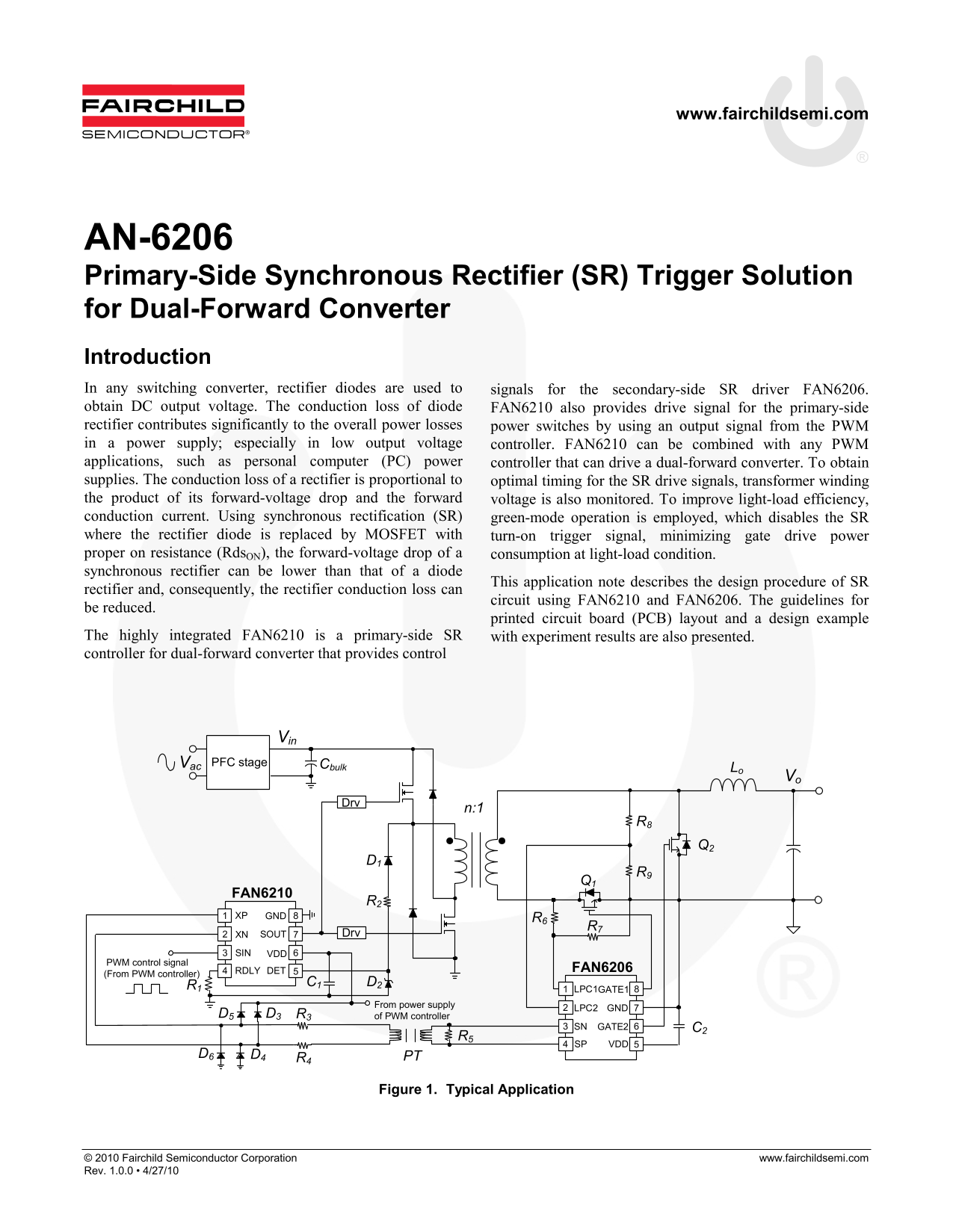
AN-6206 Primary-Side Synchronous Rectifier (SR) Trigger Solution for Dual-Forward Converter Introduction In any switching converter, rectifier diodes are used to signals for the secondary-side SR driver FAN6206. obtain DC output voltage. The conduction loss of diode FAN6210 also provides drive signal for the primary-side rectifier contributes significantly to the overall power losses power switches by using an output signal from the PWM in a power supply; especially in low output voltage controller. FAN6210 can be combined with any PWM applications, such as personal computer (PC) power controller that can drive a dual-forward converter. To obtain supplies. The conduction loss of a rectifier is proportional to optimal timing for the SR drive signals, transformer winding the product of its forward-voltage drop and the forward voltage is also monitored. To improve light-load efficiency, conduction current. Using synchronous rectification (SR) green-mode operation is employed, which disables the SR where the rectifier diode is replaced by MOSFET with turn-on trigger signal, minimizing gate drive power proper on resistance (Rds ON), the forward-voltage drop of a consumption at light-load condition. synchronous rectifier can be lower than that of a diode
This application note describes the design procedure of SR
rectifier and, consequently, the rectifier conduction loss can
circuit using FAN6210 and FAN6206. The guidelines for
be reduced.
printed circuit board (PCB) layout and a design example
The highly integrated FAN6210 is a primary-side SR with experiment results are also presented. controller for dual-forward converter that provides control
PFC stage Vac Cbulk
Lo Vo
FAN6210
XP GND R6
XN SOUT Drv
SIN VDD
PWM control signal
RDLY DET FAN6206
(From PWM controller)
LPC1GATE1
From power supply
LPC2 GND
D5 D3 R3 of PWM controller
SN GATE2 C2
SP VDD
D6 D4 PT
Figure 1. Typical Application
© 2010 Fairchild Semiconductor Corporation www.fairchildsemi.com Rev. 1.0.0 • 4/27/10
Page Summary Contents For Fairchild AN-6206 User's Manual
Manual Details
| Brand | Fairchild |
|---|---|
| Pages | 9 |
| File Size | 546.54 KB |
| Published | June 22, 2026 |
Enter the captcha to get the download link:

Frequently Asked Questions
How does synchronous rectification improve efficiency compared to diodes?
It replaces rectifier diodes with MOSFETs, which reduces conduction loss and minimizes gate drive power consumption, enhancing light-load efficiency.
What resistors are used on the secondary side of a FAN6206 application?
The resistor R connected between the SP and SN pins is recommended to have a value of 1kΩ~10kΩ for most applications.
What components protect the XP and XN pins of the FAN6210?
To protect against transient voltage spikes, resistors (R) and diodes (D) are required on those pins.
What is the recommended resistor range for the FAN6210's current limiting application?
It is typical to use 10kΩ~33kΩ for the resistor R connected between the SOUT signal and the relevant pin.