Fairchild 74LVC14 Data Handbook
Summary
This low voltage hex inverter IC provides six robust inverting gates featuring highly accurate Schmitt Trigger inputs and 5V input tolerance. Ideal for designers building modern, low-power CMOS logic circuits across 2.5V to 5V systems. The accompanying manual serves as a comprehensive guide, detailing key performance indicators such as detailed electrical characteristics, absolute maximum ratings, output drive capabilities, and recommended operating conditions necessary for precise circuit integration.
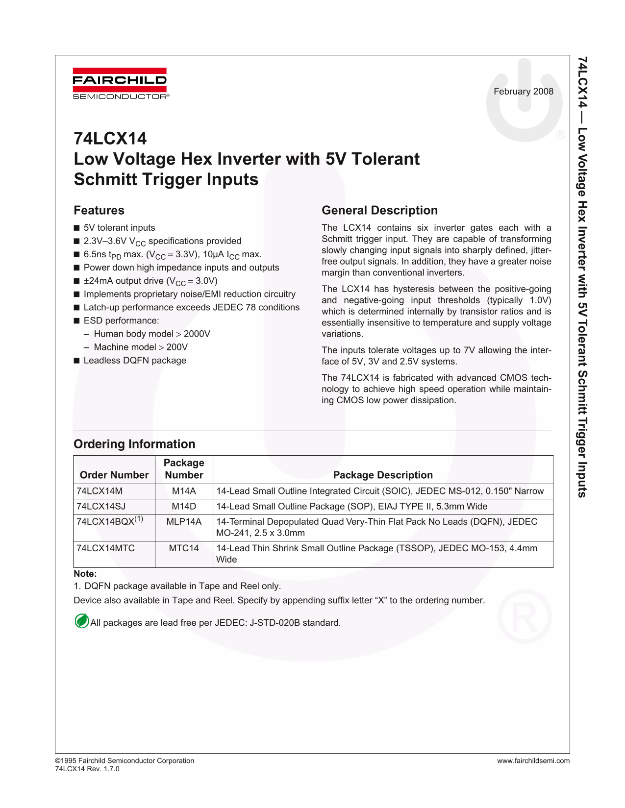
Page 1 Text Content
74L 14 — Vo ltag e H ex Inverter w ith 5V To leran t S ch itt Trig er In ts
February 2008
74LCX14 Low Voltage Hex Inverter with 5V Tolerant Schmitt Trigger Inputs Features General Description 5V tolerant inputs The LCX14 contains six inverter gates each with a
2.3V–3.6V VCC specifications provided Schmitt trigger input. They are capable of transforming slowly changing input signals into sharply defined, jitter-
6.5ns t PD max. (VCC = 3.3V), 10µA ICC max.
free output signals. In addition, they have a greater noise
Power down high impedance inputs and outputs
margin than conventional inverters.
±24m A output drive (VCC = 3.0V)
The LCX14 has hysteresis between the positive-going
Implements proprietary noise/EMI reduction circuitry
and negative-going input thresholds (typically 1.0V)
Latch-up performance exceeds JEDEC 78 conditions
which is determined internally by transistor ratios and is
ESD performance: essentially insensitive to temperature and supply voltage
– Human body model > 2000V variations.
– Machine model > 200V
The inputs tolerate voltages up to 7V allowing the inter-
Leadless DQFN package face of 5V, 3V and 2.5V systems.
The 74LCX14 is fabricated with advanced CMOS tech- nology to achieve high speed operation while maintain- ing CMOS low power dissipation.
Ordering Information
Package
Order Number Number Package Description 74LCX14M M14A 14-Lead Small Outline Integrated Circuit (SOIC), JEDEC MS-012, 0.150" Narrow 74LCX14SJ M14D 14-Lead Small Outline Package (SOP), EIAJ TYPE II, 5.3mm Wide
74LCX14BQX(1) MLP14A 14-Terminal Depopulated Quad Very-Thin Flat Pack No Leads (DQFN), JEDEC
MO-241, 2.5 x 3.0mm
74LCX14MTC MTC14 14-Lead Thin Shrink Small Outline Package (TSSOP), JEDEC MO-153, 4.4mm
Note: 1. DQFN package available in Tape and Reel only. Device also available in Tape and Reel. Specify by appending suffix letter “X” to the ordering number.
All packages are lead free per JEDEC: J-STD-020B standard.
©1 995 Fairchild Semiconductor Corporation www.fairchildsemi.com 74L CX14 Rev. 1.7.0
Page Summary Contents For Fairchild 74LVC14 Data Handbook
Manual Details
| Brand | Fairchild |
|---|---|
| Pages | 13 |
| File Size | 784.02 KB |
| Published | July 06, 2026 |
Enter the captcha to get the download link:

Frequently Asked Questions
What specific signal quality benefit do I get from the Schmitt trigger inputs?
They convert slowly changing input signals into sharply defined, jitter-free output signals and provide hysteresis.
How high a voltage can this chip safely tolerate at the inputs?
The inputs are inherently tolerant to voltages up to 7V, making it suitable for 5V, 3V, and 2.5V systems.
If I leave certain inverter gates unused, what is required for proper operation?
Unused inputs must be held either HIGH or LOW; they may not float.
Can this component be used in critical life support medical devices?
No, its use is not authorized for life support systems without the express written approval of Fairchild Semiconductor Corporation.