Fairchild 74F132 Data Handbook
Summary
This integrated circuit provides four robust 2-input NAND Schmitt Triggers, which are essential for reliable signal conditioning. These chips utilize positive feedback to transform slow or noisy input transitions into sharply defined, jitter-free digital signals with built-in hysteresis. The manual provides comprehensive technical documentation—including detailed electrical characteristics, operating parameters, and multiple package options (SOIC/SOP)—making it a vital resource for electronics engineers and designers building complex logic circuits that require stable and clean signal integrity.
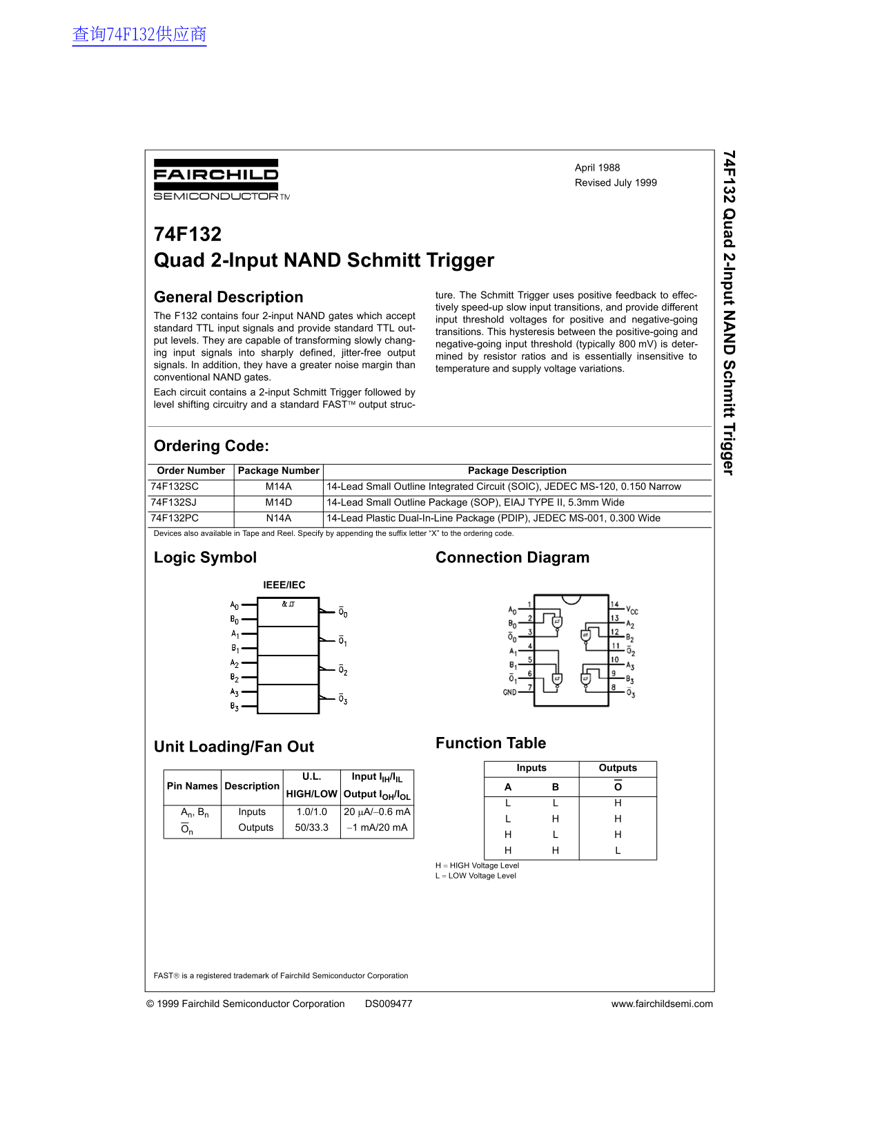
Page 1 Text Content
74F 132 Q ad 2-In t N ch itt Trig er
April 1988 Revised July 1999
74F132 Quad 2-Input NAND Schmitt Trigger
ture. The Schmitt Trigger uses positive feedback to effec-
General Description
tively speed-up slow input transitions, and provide different
The F132 contains four 2-input NAND gates which accept
input threshold voltages for positive and negative-going
standard TTL input signals and provide standard TTL out-
transitions. This hysteresis between the positive-going and
put levels. They are capable of transforming slowly chang-
negative-going input threshold (typically 800 m V) is deter-
ing input signals into sharply defined, jitter-free output
mined by resistor ratios and is essentially insensitive to
signals. In addition, they have a greater noise margin than
temperature and supply voltage variations.
conventional NAND gates. Each circuit contains a 2-input Schmitt Trigger followed by level shifting circuitry and a standard FAST output struc-
Ordering Code: Order Number Package Number Package Description 74F132SC M14A 14-Lead Small Outline Integrated Circuit (SOIC), JEDEC MS-120, 0.150 Narrow 74F132SJ M14D 14-Lead Small Outline Package (SOP), EIAJ TYPE II, 5.3mm Wide 74F132PC N14A 14-Lead Plastic Dual-In-Line Package (PDIP), JEDEC MS-001, 0.300 Wide Devices also available in Tape and Reel. Specify by appending the suffix letter “X” to the ordering code.
Logic Symbol Connection Diagram
IEEE/IEC
Function Table
Unit Loading/Fan Out
Inputs Outputs
U.L. Input IIH/IIL
Pin Names Description
HIGH/LOW Output IOH/IOL
An, Bn Inputs 1.0/1.0 20 µA/−0.6 m A
On Outputs 50/33.3 −1 m A/20 m A
H = HIGH Voltage Level L = LOW Voltage Level
FAST is a registered trademark of Fairchild Semiconductor Corporation
© 1999 Fairchild Semiconductor Corporation DS009477 www.fairchildsemi.com
Page Summary Contents For Fairchild 74F132 Data Handbook
Manual Details
| Brand | Fairchild |
|---|---|
| Pages | 4 |
| File Size | 50.22 KB |
| Published | July 12, 2026 |
Enter the captcha to get the download link:

Frequently Asked Questions
What is the recommended supply voltage range?
The recommended operating condition for the supply voltage (Vcc) is +4.5V to +5.5V.
How does the 74F132 improve input signal stability?
It uses positive feedback (Schmitt Trigger action) and hysteresis, transforming slow transitions into sharply defined, jitter-free output signals.
What package options are available for the 74F132?
Available packages include SOIC (M14A), SOP (M14D), and PDIP (N14A).
Are there any restrictions regarding life support equipment use?
Fairchild's products cannot be used as critical components in life support devices without express written approval.