Fairchild 74F114 Data Handbook
Summary
The 74F114 is a high-speed, dual JK flip-flop integrated circuit designed for robust digital timing and data storage applications. This technical manual provides comprehensive details on its functional operation, including electrical characteristics, setup/hold times, and absolute maximum ratings across various packaging options (SOIC and PDIP). It is essential reading for electronics engineers and designers who require highly reliable synchronous logic components for complex circuitry.
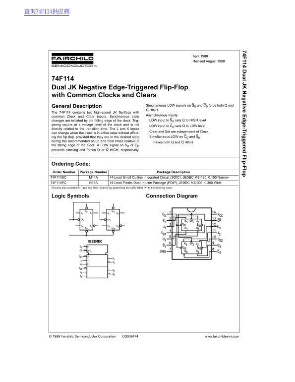
Page 1 Text Content
74F 114 D al JK eg ative E e-Trig ered lip -F lo
April 1988 Revised August 1999
74F114 Dual JK Negative Edge-Triggered Flip-Flop with Common Clocks and Clears
Simultaneous LOW signals on SD and CD force both Q and
General Description
Q HIGH.
The 74F114 contains two high-speed JK flip-flops with
Asynchronous Inputs:
common Clock and Clear inputs. Synchronous state
changes are initiated by the falling edge of the clock. Trig- LOW input to SD sets Q to HIGH level
gering occurs at a voltage level of the clock and is not
LOW input to CD sets Q to LOW level
directly related to the transition time. The J and K inputs
Clear and Set are independent of Clock
can change when the clock is in either state without affect-
ing the flip-flop, provided that they are in the desired state Simultaneous LOW on CD and SD
during the recommended setup and hold times relative to
makes both Q and Q HIGH
the falling edge of the clock. A LOW signal on SD or CD prevents clocking and forces Q or Q HIGH, respectively.
Ordering Code: Order Number Package Number Package Description 74F114SC M14A 14-Lead Small Outline Integrated Circuit (SOIC), JEDEC MS-120, 0.150 Narrow 74F114PC N14A 14-Lead Plastic Dual-In-Line Package (PDIP), JEDEC MS-001, 0.300 Wide Devices also available in Tape and Reel. Specify by appending the suffix letter “X” to the ordering code.
Logic Symbols Connection Diagram
IEEE/IEC
© 1999 Fairchild Semiconductor Corporation DS009474 www.fairchildsemi.com
Page Summary Contents For Fairchild 74F114 Data Handbook
Manual Details
| Brand | Fairchild |
|---|---|
| Pages | 6 |
| File Size | 56.26 KB |
| Published | June 05, 2026 |
Enter the captcha to get the download link:

Frequently Asked Questions
How does the 74F114 operate asynchronously?
The J and K inputs (Set and Clear) are independent of the Clock and can change at any time without affecting the flip-flop state.
What voltage range should be used for operation?
The recommended supply voltage is +4.5V to +5.5V.
Which clock edge causes functional changes on the device?
Changes are initiated by the falling (negative) edge of the clock pulse.
Is this chip approved for use in life support equipment?
No, it requires express written approval from Fairchild Semiconductor Corporation.