EMERSON Installation Manual Solenoid Valves 123620182EU Series 110 ASCO
Summary
The WPSDU pilot box is essential equipment designed for dust ignition protection in solenoid valve systems used within industrial dust collection setups. This manual provides comprehensive instructions covering proper installation, detailed electrical connection procedures, safe servicing, and routine maintenance. It is critical reading for industrial electricians and technical staff ensuring the reliable and compliant operation of your specialized ventilation machinery.
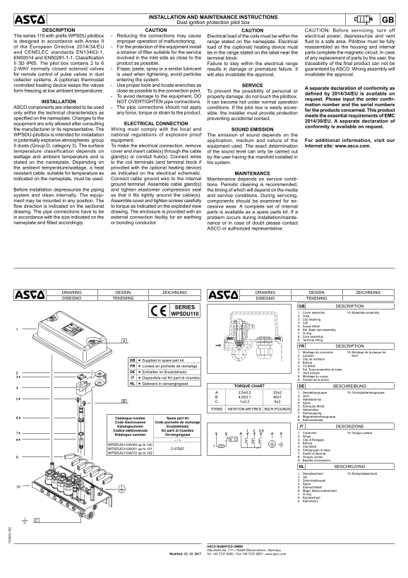
Page 1 Text Content
INSTALLATION AND MAINTENANCE INSTRUCTIONS
Dust ignition protection pilot box GB
DESCRIPTION CAUTION CAUTION CAUTION: Before servicing, turn off
The series 110 with prefix WPSDU pilotbox - Reducing the connections may cause Electrical load of the coils must be within the electrical power, depressurize and vent is designed in accordance with Annex II improper operation of malfunctioning. range stated on the nameplate. Electrical fluid to a safe area. Pilotbox must be fully of the European Directive 2014/34/EU - For the protection of the equipment install load of the (optional) heating device must reassembled as the housing and internal and CENELEC standards EN13463-1, a strainer of filter suitable for the service be in the range stated on the label near the parts complete the magnetic circuit. In case EN50014 and EN50281-1-1. Classification involved in the inlet side as close to the terminal block. of any replacement of parts by the user, the II 3D IP65. The pilot box contains 2 to 6 product as possible. Failure to stay within the electrical range traceability of the final product can not be 2-WAY normally closed solenoid valves - If tape, paste, spray or a similar lubricant results in damage or premature failure. It guaranteed by ASCO. Wrong assembly will for remote control of pulse valves in dust is used when tightening, avoid particles will also invalidate the approval. invalidate the approval. collector systems. A (optional) thermostat entering the system. controlled heating device keeps the valves - Use proper tools and locate wrenches as SERVICE
A separate declaration of conformity as
form freezing at low ambient temperatures. close as possible to the connection point. To prevent the possibility of personal or
defined by 2014/34/EU is available on
- To avoid damage to the equipment, DO property damage, do not touch the pilotbox.
request. Please input the order confir-
INSTALLATION NOT OVERTIGHTEN pipe connections. It can become hot under normal operation
mation number and the serial numbers
ASCO components are intended to be used - The pipe connections should not apply conditions. If the pilot box is easily acces-
for the products concerned. This product
only within the technical characteristics as any force, torque or strain to the product. sible, the installer must provide protection
meets the essential requirements of EMC
specified on the nameplate. Changes to the preventing accidental contact.
2014/30/EU. A separate declaration of
equipment are only allowed after consulting ELECTRICAL CONNECTION
conformity is available on request.
the manufacturer or its representative. The Wiring must comply with the local and SOUND EMISSION WPSDU-pilotbox is intended for installation national regulations of explosion proof The emission of sound depends on the in potentially explosive atmospheres. group equipment. application, medium and nature of the For additional information, visit our II dusts (Group D, category 3). The surface To make the electrical connection, remove equipment used. The exact determination Internet site: www.asco.com. temperature classification depends on cover and insert cable(s) through the cable of the sound level can only be carried out wattage and ambient temperature and is gland(s) or conduit hub(s). Connect wires by the user having the manifold installed in stated on the nameplate. Depending on to the coil terminals (and terminal block if his system. the ambient temperature/wattage, a heat provided with the optional heating device) resistant cable, suitable for temperature as as indicated on the electrical schematic. MAINTENANCE indicated on the nameplate, must be used. Connect cable ground wire to the internal Maintenance depends on service condi- ground terminal. Assemble cable gland(s) tions. Periodic cleaning is recommended, Before installation depressurize the piping and tighten elastomer compression seal the timing of which will depend on the media system and clean internally. The equip- so that it fits tightly around the cable(s). and service conditions. During servicing, ment may be mounted in any position. The Assemble cover and tighten screws carefully components should be examined for ex- flow direction is indicated on the sectional to torque as indicated on the exploded view cessive wear. A complete set of internal drawing. The pipe connections have to be drawing. The enclosure is provided with an parts is available as a spare parts kit. If a in accordance with the size indicated on the external connection facility for an earthing problem occurs during installation/mainte- nameplate and fitted accordingly. or bonding conductor. nance or in case of doubt please contact
ASCO or authorized representative.
DRAWING DESSIN ZEICHNUNG DRAWING DESSIN ZEICHNUNG DISEGNO TEKENING DISEGNO TEKENING
GB DESCRIPTION
SERIES
1. Cover assembly 10. Baseplate assembly
WPSDU110
2. Yoke 3. Clip retaining 4. Coil 5. Screw M4x8 6. Sol. Base sub-assembly 7. O-ring 8. Core assembly 9. Terminal string
FR DESCRIPTION
1. Montage du couvercle 10. Montage de la plaque de 2. Culasse fond
GB 3. Clip de maintien
Supplied in spare part kit
4. Bobine FR Livrées en pochette de rechange 5. Vis M4x8 6. Sol. Sous-ensemble de base
DE Enthalten im Ersatzteilsatz 7. Joint torique
8. Montage du noyau
IT Disponibile nel Kit parti di ricambio
9. Chaîne de la borne
NL Geleverd in vervangingsset
TORQUE CHART DE BESCHREIBUNG
2,5±0,2 22±2 1. Deckelbaugruppe 10. Grundplattenbaugruppe
4,5±0,1 40±1 2. Joch 3. Halteklammer
1±0,2 9±2 4. Spule
5. Schraube M4x8
ITEMS NEWTON.METRES INCH.POUNDS 6. Haltemutter
7. Dichtungsring 8. Magnetankerbaugruppe
Catalogue number Spare part kit
9. Klemmenleiste
Code électrovanne Code pochette de rechange Katalognummer Ersatzteilsatz IT DESCRIZIONE Codice elettrovalvola Kit parti di ricambio
1. Coperchio 10. Gruppo piastra
Katalogus nummer Vervangingsset
2. Giogo ~ / = 3. Clip di fissaggio 4. Bobina
WPSDUG110A020 up to 120
5. Vite M4x8
WPSDUG110A021 up to 121 C127837 6. Sottogruppo di base WPSDUG110A072 up to 122 7. Anello di ritenuta
8. Gruppo nucleo 9. Basetta connessioni
NL BESCHRIJVING
1. Dekseleenheid 10. Basisplaateenheid
2. Juk 3. Zekeringsbeugel 4. Spoel 5. Schroef M4x8 6. Magn. Basis subeenheid 7. O-ring 8. Kerneenheid 9. Klemmenrij
ASCO NUMATICS GMBH Otto-Hahn-Str. 7-11 / 75248 Ölbronn-Dürrn / Germany Tel. +49 7237 9960 - Fax +49 7237 9961 - www.asco.com Modified: 23. 10. 2017
Page Summary Contents For EMERSON Installation Manual Solenoid Valves 123620182EU Series 110 ASCO
Manual Details
| Brand | Emerson |
|---|---|
| Pages | 6 |
| File Size | 1.43 MB |
| Published | June 06, 2026 |
Enter the captcha to get the download link:

Frequently Asked Questions
What should be done before servicing the pilot box?
Turn off the system, depressurize and vent all electrical fluid to a safe area.
How is the proper installation of the pilot box ensured in dusty environments?
Install it in suitable enclosures (IP65 minimum) and ensure proper grounding/bonding conductor connection.
What rules must be followed when wiring or modifying the system?
Wiring must comply with local national regulations. Changes to the equipment design are only allowed after consulting the manufacturer.
Can I modify the existing pilot box connections or use it in different areas?
No, ASCO components are intended for use only within the specified technical characteristics and nameplate parameters.